


D521-Manual_EN_Rev07 2017_05_26
Page 12 of 31
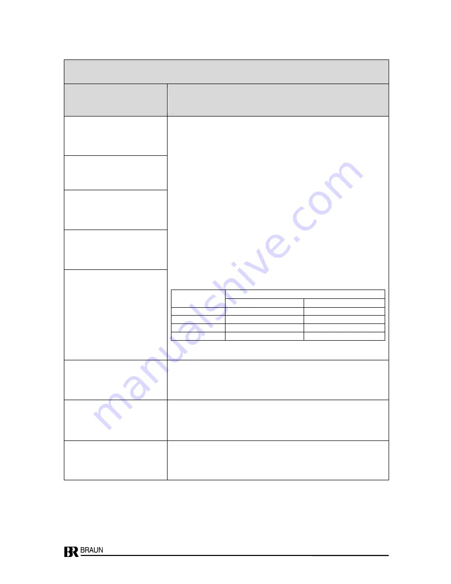
Parameter Group P01.xx
Measurement Configuration, Sensor Monitoring
Parameter No.
Meaning of Parameter
Setting Range of Parameter
Description of Parameters and their Settings
P01.00 to P01.03:
Scaling
Scaling defines the relation between the input signal frequency (in terms of
Hz), and the corresponding display (e.g. in RPM and decimal position
required by the application). Both values are freely programmable by their
decimals and numerical amount. Of course, they must refer to the same
operation level. This reference point is recommended close to the high end of
the intended operation range. In later operation, however, it may be overrun
without error.
Example:
A rotating shaft to be measured carries 36 slots. At a shaft speed of 1500
RPM, this produces a signal frequency of 1500 × 36 pulses per minute =
54,000 pulses per minute = 54,000 ÷ 60 Hz = 900 Hz. (Presuming the predi-
vider is set to 001).
Therefore, 900 (Hz) and 1500 (RPM) are the data-set to be programmed in
the corresponding program steps:
Step
P01.00 : parameter = 0 (= no decimal)
P01.01 : parameter = 00900
P01.02 : parameter = 0 (= no decimals)
P01.03 : parameter = 01500
Number of slots
Possible pair of values
Nominal Frequency (Hz)
Nominal Speed (RPM)
30
1750
3500
36
2100
3500
60
6000
6000
72
7200
6000
P01.00
Number of decimals for P01.01
Range: 0 .. 4
P01.01
Input frequency in Hz
Range: 00001 . .99999
P01.02
Number of decimals for P01.03
Range: 0 .. 4
P01.03
Speed (RPM)
Range: 00001 .. 99999
P01.04
Low end of operating range
Range: 00000 .. 99999
If the speed value falls lower than this level, the measurement will be
canceled to zero. This also applies to the analog output and the alarms.
The low end is entered directly as RPM.
P01.05
Hysteresis of the
Input Response Level
Range: 0 .. 1
Hysteresis of the input response level:
Setting:
0 : Hysteresis approx. 0.8 volts (for A5S sensors)
1 : Hysteresis approx. 0.1 volts (for MPU or NAMUR sensors)
P01.06
Reserved for future applications


