22
Ser
vi
ce
Proce
d
ure
II
:
Combust
i
on
System
T
est
i
ng
an
d
R
ep
l
acement
Ob
se
r
v
e
b
u
r
ne
r
ope
r
at
i
on
th
r
ou
gh
the
sight
g
l
ass
l
ocated
on
the
combustion
insert
mounting
f
l
ange
. N
orma
l
burner
operation
shou
l
d
ignite
smooth
l
y,
without
e
v
idence
of
coughing
or
huffing
upon
ignition
.
The
burner
f
l
ame
shou
l
d
be
a
b
l
ue
f
l
ame
near
the
burner
surface
in
a
uniform
f
l
ame
pattern
.
Occasiona
l
ye
ll
ow
or
white
streaks
are
norma
l.
N
ote:
On
th
i
s
h
i
gh
i
nput
mo
d
e
l
that
uses
meta
l
f
i
ber
mesh
burner
a
re
d
g
l
ow
from
the
burner
surface
i
s
norma
l.
120
v
o
l
t
potentia
l
exposure
. I
so
l
ate
the
app
l
iance
and
reconfirm
power
is
disconnected
using
a
mu
l
ti
-
meter
.
WA
RN
I
N
G
Continued
from
pre
v
ious
page
N
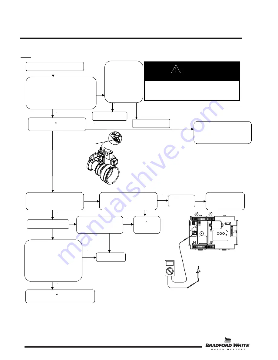
Refer
to
contro
l
board
i
ll
ustration,
is
there
2
4
VAC
between
brown
and
b
l
ue
wires
coming
out
of
the
contro
l
harness
during
the
f
l
ame
estab
l
ishing
period
?
(
N
ote
:
Contro
l
disp
l
ay
must
show
“Heating”
for
operating
status)
.
Check
to
see
brown
and
b
l
ue
wires
are
proper
l
y
connected
to
mo
l
ex
connectors
on
contro
l
harness
.
Can
you
hear
or
fee
l
gas
v
a
lv
e
energize
?
Rep
l
ace
gas
v
a
lv
e
harness
and/or
gas
v
a
lv
e
.
(See
“Gas
Va
lv
e
Rep
l
acement
Procedure”
.
)
Does
burner
l
ight
smooth
l
y,
without
e
v
idence
of
coughing
or
huffing
?
Check
for
obstruction
at
in
l
et
of
gas
v
a
lv
e
. I
s
in
l
et
free
of
obstruction
?
C
l
ear
obstruction
I
nspect
burner
tube,
(see
“Burner
Tube
I
nspection”)
.
Does
burner
stay
l
it
?
Does
burner
operate
norma
ll
y
unti
l
thermostat
is
satisfied
?
Ca
ll
for
technica
l
support
Check
f
l
ame
sensor
.
Are
there
at
l
east
1
to
5
micro
amps
(min
.
)
during
1
.
5
second
f
l
ame
pro
v
ing
period
?
(Va
l
ue
may
be
disp
l
ayed
on
the
contro
l
disp
l
ay
by
accessing
“Ser
v
ice
Mode”
.
)
System
O
.
K
.
Rep
l
ace
f
l
ame
sensor
(see
“
Fl
ame
Sensor
Rep
l
acement
Procedure”)
.
gas
v
a
lv
e/
v
entur
i
Y
Y
N
Y
Y
Y
N
N
N
N
Y
Y
N
N
Rep
l
ace
contro
l
Make
connections
N
Y
I
n
l
et
Pressure
Tap
22


