


12
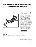
OPERATIONAL INSTRUCTIONS
RECUMBENT BIKE MODE AND ROWER MODE
Your 3 IN 1 Rower/Recumbent Bike & Strength Trainer can be used in the Recumbent Bike mode or
the Rower mode. When the
SPRING PIN (67)
locks the SEAT ASSEMBLY to the
RAIL (52)
, the Rower,
Recumbent Bike & Strength Trainer is in the Recumbent Bike mode. When the
SPRING PIN (67)
is in
the Release position, the SEAT ASSEMBLY
is not locked to the
RAIL (52)
and the
Rower, Recumbent Bike & Strength Trainer
is in the Rower mode.
RECUMBENT BIKE MODE:
Pull the knob
on the
SPRING PIN (67)
, turn it clockwise
and release the knob to allow it to lock the
seat in position. Sit on the seat and pedal
with the
PEDALS (39,41)
.
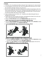
ROWER MODE:
Pull the knob on the
SPRING PIN (67)
and turn it counter-clockwise to lock it in the release position. Refer to the inset
drawing. This will allow the SEAT ASSEMBLY to slide freely on the
RAIL (52)
. To workout, sit on the
seat, place your feet on the fixed
FOOT PEDALS (46)
and pull on the
HANDLEBAR (25)
.
NOTE:
If the
FRONT STABILIZER(2)
raises off the floor during use, adjust the
STAND(43)
to a higher
position.
CAUTION:
Always verify that the
SPRING PIN (67)
is in the correct position before you begin your
workout.
SEAT ADJUSTMENT
Proper seat adjustment is important for Recumbent Bike mode.
1. Pull the knob on the
SPRING PIN (67)
and slide the SEAT ASSEMBLY forward or backward to
adjust the seat. Release the knob on the
SPRING PIN (67)
and make sure it is inserted into one of
the adjustment holes in the
RAIL (52)
.
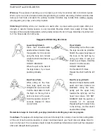
2. Sit on the seat and place your feet on the
pedals. You should be able to move through a
complete pedal stroke without locking your
knees or shifting your hips on the seat. The
seat is too close to the pedals if you have
more than a slight bend in your knees at the
bottom of the pedal stroke. The seat is too far
from the pedals if you have to completely
straighten your knees at the bottom of the pedal stroke. Refer to the illustrations below.
WARNING: Do not attempt to adjust the seat while you are on the 3 IN 1 Rower/Recumbent Bike & Strength
Trainer.
Содержание 3 IN 1 ROWER
Страница 20: ...20...


