


Service Manual 04/2010 Rev.B
120
Check the hook following
7.13.
TO REPLACE THE HOOK:
Replace the hook following
7.13.
7.15 SCREW SUPPORT TOOL
HOLDER ARM: CHECK AND
ADJUSTMENT
:
30’
:
End wrenches of 22.
L
:
Incorrect screw adjustment may cause the
following malfunctions:
1. Unsuccessful
hook
clamping.
2. Slow or locking of tool holder arm movement.
TO CHECK THE ADJUSTMENT:
Turn the machine on.
Move the tool holder arm from the left to right
‘till end of the stroke and verify if the screw
head gets a contact with the saddle.
If there is contact the screw must be adjusted.
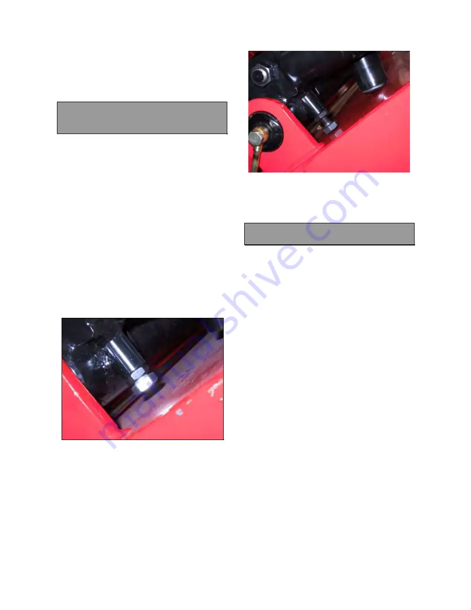
TO ADJUST THE SCREW
Turn on the machine.
Lose the support screw and clamp the tool
holder (Fig.285).
Fig.285
Position the screw on the closest point to the
saddle.
Turn the screw ‘till to have its head in contact
with the saddle and then turn it back ¾ of a
turn (Fig.286).
Check if the hook clamps the saddle easily: if
not turn the screw ¼ more of a turn in order to
increase the clearance.
Fig.286
Lock firmly the nut.
Move the tool holder arm to verify if the screw
is well adjusted.
7.16 KING 5600 TOOL OLDER ARM:
CHECK AND REPLACEEMENT
:
3h
:
End wrenches 13,19,22 and 30mm, Allen
wrench of 4 and 6mm, rubber hammer.
L
:
The tool holder arm must be change in case
of mechanical breakage only.
TO CHECK THE ARM:
If the tool holder arm cannot be easily
clamped or if it shows mechanical breakages,
it must be replaced.
TO REPLACE THE ARM:
Remove the mount – dismount tool, the tube
with spring and the hook
7.13.
Remove the tool holder cylinder
6.16.
Take out the defective arm.
Install the new arm (Fig.287).
Mount the tool holder cylinder
6.16.
Place the arm on the saddle guide.
Move by hands the arm from left to right: if it is
hard to be moved the half –cap needs to be
adapted by grinding machine (Fig.287).
Mount and make the hook adjustment
7.13.
Mount the tube with spring
7.13.
Содержание KING 5600
Страница 2: ...Service Manual 04 2010 Rev B 2 UPDATING GUIDE Release B of 02 04 2010 Removed 50 or 60 Hz At page 49...
Страница 9: ...Service Manual 04 2010 Rev B 9 3 1 ELECTRIC DIAGRAM FOR CE PROVED KING 5600 Fig 16...
Страница 10: ...Service Manual 04 2010 Rev B 10 Fig 17...
Страница 11: ...Service Manual 04 2010 Rev B 11 Fig 18...
Страница 12: ...Service Manual 04 2010 Rev B 12 Fig 19...
Страница 13: ...Service Manual 04 2010 Rev B 13 Fig 20...
Страница 14: ...Service Manual 04 2010 Rev B 14 Fig 21...
Страница 15: ...Service Manual 04 2010 Rev B 15 Fig 22...
Страница 16: ...Service Manual 04 2010 Rev B 16 Fig 23...
Страница 17: ...Service Manual 04 2010 Rev B 17 3 2 ELECTRIC DIAGRAM FOR KING SUPPLIED AT 200V 3PH 60Hz Fig 24...
Страница 18: ...Service Manual 04 2010 Rev B 18 Fig 25...
Страница 19: ...Service Manual 04 2010 Rev B 19 Fig 26...
Страница 20: ...Service Manual 04 2010 Rev B 20 Fig 27...
Страница 21: ...Service Manual 04 2010 Rev B 21 Fig 28...
Страница 22: ...Service Manual 04 2010 Rev B 22 Fig 29...
Страница 23: ...Service Manual 04 2010 Rev B 23 Fig 30...
Страница 24: ...Service Manual 04 2010 Rev B 24 Fig 31...
Страница 25: ...Service Manual 04 2010 Rev B 25 3 3 ELECTRIC DIAGRAM FOR CE APPROVED KING 5600R Fig 32...
Страница 26: ...Service Manual 04 2010 Rev B 26 Fig 33...
Страница 27: ...Service Manual 04 2010 Rev B 27 Fig 34...
Страница 28: ...Service Manual 04 2010 Rev B 28 Fig 35...
Страница 29: ...Service Manual 04 2010 Rev B 29 Fig 36...
Страница 30: ...Service Manual 04 2010 Rev B 30 Fig 37...
Страница 31: ...Service Manual 04 2010 Rev B 31 Fig 38...
Страница 32: ...Service Manual 04 2010 Rev B 32 Fig 39...
Страница 33: ...Service Manual 04 2010 Rev B 33 3 4ELECTRIC DIAGRAM FOR KING 5600R SUPPLIED AT 200V 3PH 60HZ Fig 40...
Страница 34: ...Service Manual 04 2010 Rev B 34 Fig 41...
Страница 35: ...Service Manual 04 2010 Rev B 35 Fig 42...
Страница 36: ...Service Manual 04 2010 Rev B 36 Fig 43...
Страница 37: ...Service Manual 04 2010 Rev B 37 Fig 44...
Страница 38: ...Service Manual 04 2010 Rev B 38 Fig 45...
Страница 39: ...Service Manual 04 2010 Rev B 39 Fig 46...
Страница 40: ...Service Manual 04 2010 Rev B 40 Fig 47...
Страница 41: ...Service Manual 04 2010 Rev B 41 3 5 HYDRAULIC DIAGRAM FOR CE APPROVED KING 5600 Fig 48...
Страница 42: ...Service Manual 04 2010 Rev B 42 Fig 49...
Страница 43: ...Service Manual 04 2010 Rev B 43 3 6HYDRAULIC DIAGRAM FOR KING 5600 Fig 50...
Страница 44: ...Service Manual 04 2010 Rev B 44 Fig 51...
Страница 45: ...Service Manual 04 2010 Rev B 45 3 7 HYDRAULIC DIAGRAM FOR CE APPROVED KING 5600R Fig 52...
Страница 46: ...Service Manual 04 2010 Rev B 46 Fig 53...
Страница 47: ...Service Manual 04 2010 Rev B 47 3 8 HYDRAULIC DIAGRAM FOR MACHINE NON CE KING 5600R Fig 54...
Страница 48: ...Service Manual 04 2010 Rev B 48 Fig 55...
Страница 138: ...Service Manual 04 2010 Rev B 138 BLANK PAGE...
Страница 139: ...Service Manual 04 2010 Rev B 139 BLANK PAGE...


