


Service Manual 04/2010 Rev.B
109
SADDLE IS VERY HAEVY AND
IT MUST BE HANDLEDED WITH
DECISION. ITS DROPPING MAY
CAUSE FEET INJURIES.
IMPORTANT!
AS THE SADDLE IS DISMOUNTED THE
CONTROL OF ITS BUSHINGS IS
RECOMMENDED.
Replace the defective slides
7.2.
Lubricate the cabinet guide and the bushings
with black grease while the bar must
lubricated with standard grease.
Install the saddle on the cabinet and lock the
bolt of Fig.245 with green loctite.
Install the saddle pin #5 (
6.9 Fig.177 and
178).
Close the saddle ‘till end of the stroke.
Install the bar with the slides and make the
saddle regulation
7.2.
Install the tool holder assy on the machine.
Install the tool holder cylinder
6.16
Install the steel oil hose.
Install the mount dismount tool.
Install the mobile plate on the saddle
6.6
Check if the machine works fine.
7.4 KING 5600 SADDLE BUSHINGS:
CHECK AND REPLACEMENT
:
5h
:
End wrenches 9,10,13,17,19,22,24,30mm,
17 and 22mm socket wrench, manometer,
steel and rubber hammers, Tool for removal
of cylinder pin, Wrench adjustment of saddle
clearance.
L
:
Incorrect saddle adjustment may cause the
following malfunctions:
1. Excess of saddle play.
2. Incorrect distance between tool and rim.
TO CHECK THE BUSHINGS:
Turn on the machine.
Open the saddle ‘till end of stroke.
Take a long tyre lever and lift up the saddle
(Fig. 247): if it shows a lot of play the bushings
are worn and they must be replaced.
Fig.247
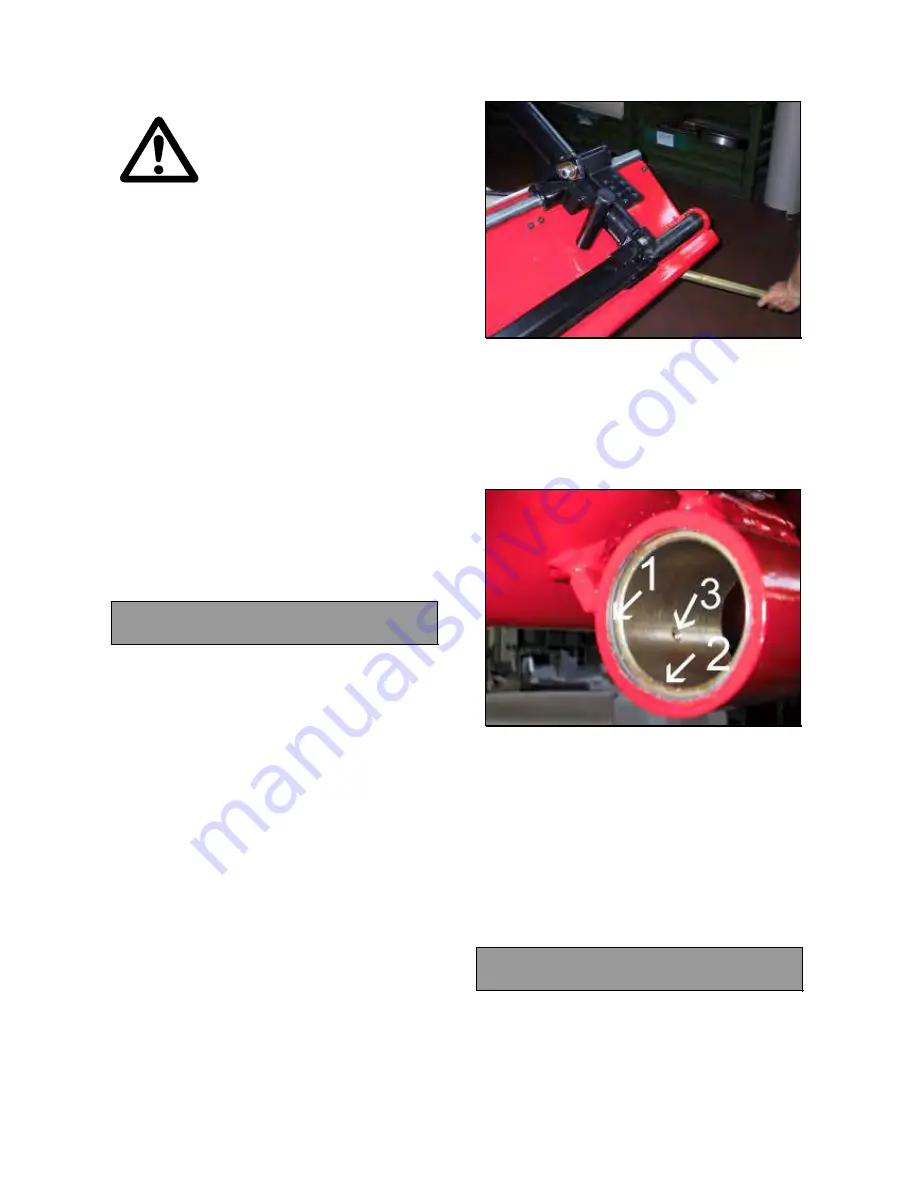
TO REPLACE THE SADDLE BUSHINGS:
Remove the saddle from the cabinet
7.3.
Remove the rings #1 from the bushings
(Fig.248).
Remove the defective bushings #2 (Fig.241).
Fig.248
Install the new bushings.
Insert the seeger rings.
Make the hole #3 (Fig.248) for the greaser.
Make sure that the bar can be easily
inserted through both bushings. If not
provide to machine the bushings by using
55mm diameter tool.
Install the saddle on the cabinet
7.3.
Regulate
the
saddle 7.2.
Check if the machine works fine.
7.5 KING 5600R ROBOTIC ROTATION:
CHECK AND ADJUSTEMENT
:
1h
:
End wrench of 30mm,Allen wrench of 4,
green loctite.
L
:
The incorrect robotic rotation may cause the
following malfunctions:
1. Incomplete mount dismount tool rotation.
Содержание KING 5600
Страница 2: ...Service Manual 04 2010 Rev B 2 UPDATING GUIDE Release B of 02 04 2010 Removed 50 or 60 Hz At page 49...
Страница 9: ...Service Manual 04 2010 Rev B 9 3 1 ELECTRIC DIAGRAM FOR CE PROVED KING 5600 Fig 16...
Страница 10: ...Service Manual 04 2010 Rev B 10 Fig 17...
Страница 11: ...Service Manual 04 2010 Rev B 11 Fig 18...
Страница 12: ...Service Manual 04 2010 Rev B 12 Fig 19...
Страница 13: ...Service Manual 04 2010 Rev B 13 Fig 20...
Страница 14: ...Service Manual 04 2010 Rev B 14 Fig 21...
Страница 15: ...Service Manual 04 2010 Rev B 15 Fig 22...
Страница 16: ...Service Manual 04 2010 Rev B 16 Fig 23...
Страница 17: ...Service Manual 04 2010 Rev B 17 3 2 ELECTRIC DIAGRAM FOR KING SUPPLIED AT 200V 3PH 60Hz Fig 24...
Страница 18: ...Service Manual 04 2010 Rev B 18 Fig 25...
Страница 19: ...Service Manual 04 2010 Rev B 19 Fig 26...
Страница 20: ...Service Manual 04 2010 Rev B 20 Fig 27...
Страница 21: ...Service Manual 04 2010 Rev B 21 Fig 28...
Страница 22: ...Service Manual 04 2010 Rev B 22 Fig 29...
Страница 23: ...Service Manual 04 2010 Rev B 23 Fig 30...
Страница 24: ...Service Manual 04 2010 Rev B 24 Fig 31...
Страница 25: ...Service Manual 04 2010 Rev B 25 3 3 ELECTRIC DIAGRAM FOR CE APPROVED KING 5600R Fig 32...
Страница 26: ...Service Manual 04 2010 Rev B 26 Fig 33...
Страница 27: ...Service Manual 04 2010 Rev B 27 Fig 34...
Страница 28: ...Service Manual 04 2010 Rev B 28 Fig 35...
Страница 29: ...Service Manual 04 2010 Rev B 29 Fig 36...
Страница 30: ...Service Manual 04 2010 Rev B 30 Fig 37...
Страница 31: ...Service Manual 04 2010 Rev B 31 Fig 38...
Страница 32: ...Service Manual 04 2010 Rev B 32 Fig 39...
Страница 33: ...Service Manual 04 2010 Rev B 33 3 4ELECTRIC DIAGRAM FOR KING 5600R SUPPLIED AT 200V 3PH 60HZ Fig 40...
Страница 34: ...Service Manual 04 2010 Rev B 34 Fig 41...
Страница 35: ...Service Manual 04 2010 Rev B 35 Fig 42...
Страница 36: ...Service Manual 04 2010 Rev B 36 Fig 43...
Страница 37: ...Service Manual 04 2010 Rev B 37 Fig 44...
Страница 38: ...Service Manual 04 2010 Rev B 38 Fig 45...
Страница 39: ...Service Manual 04 2010 Rev B 39 Fig 46...
Страница 40: ...Service Manual 04 2010 Rev B 40 Fig 47...
Страница 41: ...Service Manual 04 2010 Rev B 41 3 5 HYDRAULIC DIAGRAM FOR CE APPROVED KING 5600 Fig 48...
Страница 42: ...Service Manual 04 2010 Rev B 42 Fig 49...
Страница 43: ...Service Manual 04 2010 Rev B 43 3 6HYDRAULIC DIAGRAM FOR KING 5600 Fig 50...
Страница 44: ...Service Manual 04 2010 Rev B 44 Fig 51...
Страница 45: ...Service Manual 04 2010 Rev B 45 3 7 HYDRAULIC DIAGRAM FOR CE APPROVED KING 5600R Fig 52...
Страница 46: ...Service Manual 04 2010 Rev B 46 Fig 53...
Страница 47: ...Service Manual 04 2010 Rev B 47 3 8 HYDRAULIC DIAGRAM FOR MACHINE NON CE KING 5600R Fig 54...
Страница 48: ...Service Manual 04 2010 Rev B 48 Fig 55...
Страница 138: ...Service Manual 04 2010 Rev B 138 BLANK PAGE...
Страница 139: ...Service Manual 04 2010 Rev B 139 BLANK PAGE...


