background image

21


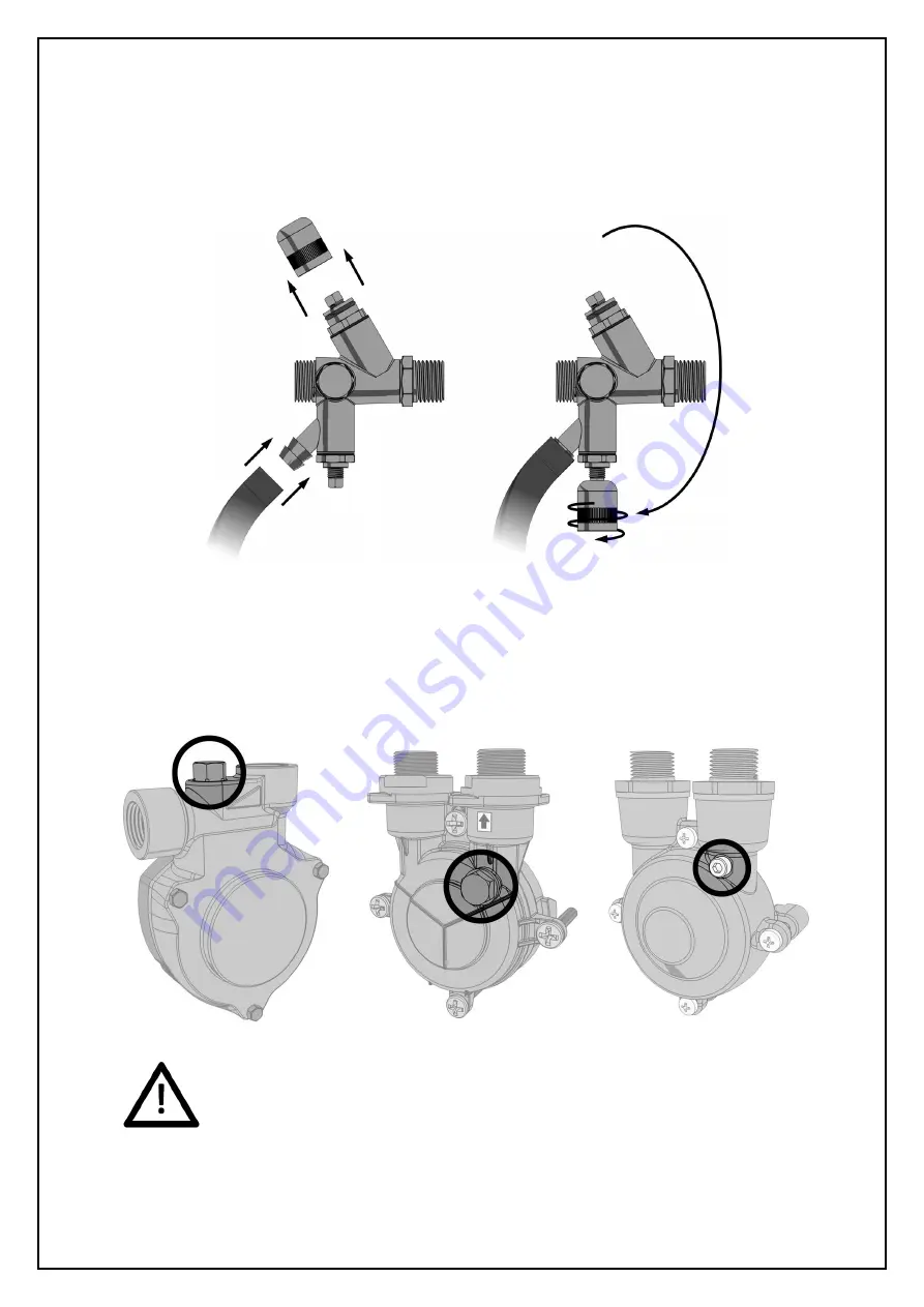
Attach a length of hose to the hose tail on the drain valve and put the other end to drain. Then, using 
the cap off the isolation valve, open the drain valve: 


Locate the bleed screw on the pump. The following diagrams show examples of typical bleed screw 
locations for most pumps: 


Do not use excessive force when tightening the bleed screw as this may damage the 
pump casing.


Содержание AX1-2.5E

Страница 1: ...ssurisation Equipment AX Models AX1 2 5E AX2 2 5E AX1 5E AX2 5E PF Models PF1 2 5E PF2 2 5E PF1 5E PF2 5E Midi Models MD1 2 5E MD2 2 5E MD1 5E MD2 5E Digifiller Digifiller 0 5 Digifiller 1 0 Digifiller 1 5 Digifiller 2 0 Mini Models MX1 3E MX2 3E ...

Страница 2: ...quirements 10 Electrical Power Supply 11 Fault Contacts 12 Power Filter 13 Commissioning 14 Pre Commissioning Checklist 14 Controller Overview 15 Controller Programming 16 Hydraulic Commissioning 20 Commissioning Record 25 Operation 26 Fault Codes 26 Shutdown Procedure 27 Start Up Procedure 27 Troubleshooting 28 Maintenance 31 Wiring Diagram 33 Service Log 34 Spares 36 Electrical Items All Models ...

Страница 3: ...ORTANT Important information intended to ensure that the equipment functions correctly USEFUL Useful information which may be helpful but is not necessarily required for the unit to function correctly Typography This manual makes use of different typography to identify different types of information Italics Key words and phrases Round Brackets Used to identify a button on the digital controller Sq...

Страница 4: ... tank 1 which is filled from the mains water supply 2 via a float operated valve 3 The break tank is fitted with an overflow 4 in case the break tank overfills and a weir overflow 5 in case the primary overflow fails The pressurisation unit is connected into the heating system 6 via an isolation valve 7 The pressure sensor 8 monitors the system pressure If the pressure sensor detects a drop in pre...

Страница 5: ...supply pipe must be flushed before connection to the pressurisation unit All pipe connections must be made with appropriate jointing compound PTFE tape If PTFE tape is used care must be taken to ensure that the tape does not obstruct the orifice of the fitting Non return valves pressure reducing valves and RPZ valves must not be installed between the pressurisation unit and the heating cooling sys...

Страница 6: ...he appropriate flow restrictor is based on the maximum mains water pressure at the point of installation Please refer to the following table for selection Mains Water Pressure Requirement 1 4 Bar Low Pressure Restrictor coloured Above 4 Bar High Pressure Restrictor white factory fitted If no restrictor is required the filter must be removed from one of the restrictors and installed on its own The ...

Страница 7: ... 22mm Guidance on drainage requirements should be obtained from the local water authority System Connection BSP M 15mm The pressurisation unit and expansion vessel should be connected to the system at the same point The point of connection should be in the system return on the suction side of the circulation pump Non return valves pressure reducing valves and RPZ valves must not be used ...

Страница 8: ...ow 22mm Guidance on drainage requirements should be obtained from the local water authority System Connection BSP M 15mm The pressurisation unit and expansion vessel should be connected to the system at the same point The point of connection should be in the system return on the suction side of the circulation pump Non return valves pressure reducing valves and RPZ valves must not be used ...

Страница 9: ...w 22mm Guidance on drainage requirements should be obtained from the local water authority System Connection BSP M 15mm The pressurisation unit and expansion vessel should be connected to the system at the same point The point of connection should be in the system return on the suction side of the circulation pump Non return valves pressure reducing valves and RPZ valves must not be used Min 50mm ...

Страница 10: ...2mm Guidance on drainage requirements should be obtained from the local water authority System Connection BSP F The pressurisation unit and expansion vessel should be connected to the system at the same point The point of connection should be in the system return on the suction side of the circulation pump Non return valves pressure reducing valves and RPZ valves must not be used Min 50mm ...

Страница 11: ...pressurisation unit must be connected into the fused terminal block as shown below On some larger models the fused terminal block is replaced by a fused spur If this is the case the power supply must be connected into the fused spur as shown below It is recommended to supply power to the pressurisation unit via a lockable isolator This should be installed within 2m of the equipment This equipment ...

Страница 12: ...to a BMS system or as a boiler interlock These are terminals 1 12 located on the digital controller With the exception of the Common Alarm it is possible to convert all other fault contacts to normally closed For further information please refer to the commissioning section of this manual ...

Страница 13: ...is fitted with a backup generator If required a power filter can be purchased separately using product code FC100 The power filter must be connected between the transformer and the digital controller on the 12VAC line as shown in the diagram below Because the filter is installed on the secondary side of the transformer the polarity of the connections does not matter For the filter to function corr...

Страница 14: ...ing system is fitted with a safety valve and expansion vessel The following conditions must be met for the pressurisation unit and heating cooling system to function correctly If these conditions have not been met it is not advisable to proceed with the commissioning process The system connection has been made into the system return header pump suction There are no non return valves pressure reduc...

Страница 15: ... in the menu items available Old Controller Design On older models the design of the digital controller is visualy different The internal components are identical and the button functions remain the same The old controller design is shown below When in normal operation the controller will display the current system pressure If a fault occurs the controller will display a fault code and produce an ...

Страница 16: ... SET to move onto the next digit Repeat for all digits then once the correct code is shown on the display press SET to enter the programming menu Once a correct code has been entered the first option COLD FILL will appear on the screen Once in the menu the value of the current menu item can be changed using the and buttons Once the current value has been set pressing the SET button will move on to...

Страница 17: ...0 5 Bar below the COLD FILL pressure It is not possible to enter a value higher than the current COLD FILL value 0 5 Bar 4 DIFFERENTIAL The differential between the cut in and cut out pressures of the pressurisation pumps The cut in pressure will be equal to the COLD FILL pressure minus the differential pressure For example if the COLD FILL pressure is set to 1 5 bar and the differential set to 0 ...

Страница 18: ... unit will register an EXCESSIVE DEMAND alarm Enabling this option may cause false alarms on some systems NO 14 SERVICE When enabled a service reminder will be displayed after 12 months from when the option was enabled To reset the service reminder set the value to NO and exit the menu Then re enter the menu and set the value to YES again NO 15 FILL SYSTEM When enabled the LOW PRESSURE and FLOOD L...

Страница 19: ...ent NO 21 GLYCOL UNIT Enables the low glycol level switch This option should only be enabled on glycol pressurisation units NO 22 ID NUMBER A user configurable identification number This option does not serve any functional purpose 12 23 RELAY INVERSION When enabled all normally open fault contacts i e all except the common alarm are converted to normally closed NO 24 OVERRUN Allows the pump to co...

Страница 20: ...e float valve operates for the first time it may not close immediately causing the break tank to overfill Once the internals of the valve have been fully wetted this should not occur again 2 Bleeding Pumps This step is only necessary for AX PF Digifiller and Midi units For Mini units move on to the next step Make sure that the internal isolation valve within the pressurisation unit is closed by fo...

Страница 21: ...to drain Then using the cap off the isolation valve open the drain valve Locate the bleed screw on the pump The following diagrams show examples of typical bleed screw locations for most pumps Do not use excessive force when tightening the bleed screw as this may damage the pump casing ...

Страница 22: ...ce pump 2 to run If the controller is older than V6 1 then there is no way to force pump 2 to run via the controller To force the second pump to run the unit must be isolated and the live wires in terminals 13 and 14 must be swapped over The second pump then becomes pump 1 and can be forced to run via the controller To bleed the pumps the pumps must be started Then while the pump is running the bl...

Страница 23: ... either increase the system pressure using a filling loop or enable the system fill option on the pressurisation unit If the system pressure is above the high pressure alarm setting the controller will display a HIGH PRESSURE fault To clear this fault use a suitable drain point to remove water from the system until the system pressure equals the cold fill pressure If the system pressure is above t...

Страница 24: ...t point a low pressure fault will be displayed and the pumps will not run The pressurisation unit is not designed to cope with a sudden loss of system pressure which would be symptomatic of a catastrophic failure such as a burst pipe Once the system pressure has fallen below the cold fill setting by an amount equal to the differential setting the pump should start refilling the system The pump wil...

Страница 25: ...D LIMIT Minutes SENSOR TYPE 0 1 2 Delete as appropriate PUMP 1 COUNT SPC CONTROLLER YES NO Delete as appropriate PUMP 1 HOURS GLYCOL UNIT YES NO Delete as appropriate PUMP 2 COUNT ID NUMBER PUMP 2 HOURS RELAY INVERSION YES NO Delete as appropriate ALARM COUNT OVERUN POWER INTERRUPTED PRESSURE ALARM AUTO RESET YES NO Delete as appropriate PULSE YES NO Delete as appropriate CASCADE EXCESSIVE START Y...

Страница 26: ...e is below the LOW PRESSURE set point User Defined HIGH PRESSURE The system pressure is above the HIGH PRESSURE set point User Defined LOW H20 The break tank low level float switch has been activated Auto Reset HIGH H20 The break tank high level float switch has been activated Auto Reset P1 FAIL The controller has detected a fault incorrect current draw on the respective pump Manual Reset P2 FAIL ...

Страница 27: ... the break tank Start Up Procedure Attention This procedure is for restarting the unit after being shutdown as described above For initial start up and commissioning procedures please refer to the Commissioning section of this manual To restart the pressurisation unit please follow the steps below 1 Perform a visual inspection of the unit and installation to check for signs of damage 2 Check the b...

Страница 28: ...OLLER option is enabled Disable the SPC CONTROLLER option The LOW PRESSURE set point is too high Review the system specifications HIGH PRESSURE fault is displayed The internal isolation valve within the unit is closed Open the internal isolation valve The system pressure has risen above the HIGH PRESSURE set point Decrease system pressure using a suitable drain point The expansion vessel has faile...

Страница 29: ...rical connection has been made into terminals 21 22 Remove all non standard electrical connections The digital controller has failed Replace digital controller Pressure reading does not match actual system pressure The internal isolation valve within the unit is closed Open the internal isolation valve The SENSOR TYPE option is set incorrectly Review SENSOR TYPE setting A non return valve has been...

Страница 30: ...rn valve The expansion vessel has failed or lost its pre charge Check the expansion vessel pre charge and re charge if necessary The point of connection of the unit is too far away from the expansion vessel Move unit expansion vessel connection points closer together The buttons on the digital controller do not respond The plastic housing of the digital controller has come apart and the PCB has mo...

Страница 31: ...eps a log of the number of pump starts and total hours run for each pump as well as the number of alarm activations and power interruptions It is advisable to take a note of these figures when servicing the unit as they may be helpful in diagnosing potential issues Fields are provided in the service log for these figures It is advisable to scroll through all the settings including engineers settin...

Страница 32: ...k the tank should be drained down and cleaned Check Strainer AX PF units only AX and PF pressurisation units are fitted with a mesh strainer in the connection at the bottom of the break tank This should be removed and inspected Depending on the condition this part may need to be cleaned or replaced Check Expansion Vessel Pre Charge Many of the problems experienced with pressurisation equipment can...

Страница 33: ...33 Wiring Diagram ...

Страница 34: ...34 Service Log This service log should be completed by the service engineer after each annual service ...

Страница 35: ...35 ...

Страница 36: ...doubt about the compatibility of replacement parts please contact AMS BSS Technical Leicester AMS Wigan AMS Spares Service Nottingham Tel 0116 262 3232 Tel 0870 609 2101 Tel 0870 850 3886 Email enquires bssgroup com Email amspumps bssgroup com Email amsse bssgroup com Electrical Items All Models Image for indication only Description Part Code 1 Digital Controller MICRO CONTROL 2 12V Mini Transform...

Страница 37: ...n only Description Part Code 1 Pump See Datasheet 2 Non Return Valve FC SC1 4 Pressure Transducer 0 10 Bar 1 6V 1 6V TRANSDUCER 5 Combined Isolation Drain Valve FCCG NO 6 Float Valve BSS P33 7 Overflow Connection BSS M021 8 Mesh Strainer N A 9 Float Switch BSS RO12 ...

Страница 38: ...ode 1 Pump See Datasheet 2 Non Return Valve FC SC1 3 Braided Hose BSS FLEXHOSE 4 Pressure Transducer 0 10 Bar 1 6V 1 6V TRANSDUCER 5 Combined Isolation Drain Valve FCCG NO 6 Float Valve BSS P33 7 Overflow Connection BSS M021 8 Mesh Strainer N A 9 Float Switch BSS RO12 10 Ball Valve BSS M005 ...

Страница 39: ...cription Part Code 1 Pump See Datasheet 2 Non Return Valve FC SC1 3 Braided Hose BSS FLEXHOSE 4 Pressure Transducer 0 10 Bar 1 6V 1 6V TRANSDUCER 5 Mini Float Valve BSS M003 6 Combined Isolation Drain Valve FCCG NO 7 Overflow Connection BSS M021 8 Mesh Strainer N A 9 Float Switch BSS R012 ...

Страница 40: ...0 Bar 1 6V 1 6V TRANSDUCER 3 Ball Valve BSS M005 4 Overflow Connection BSS M021 5 Mini Float Valve BSS M003 6 Float Switch BSS R012 7 8mm Poly tube BSS M015 8 BSP M x 8mm Push Fit BSS M007 9 8mm Push Fit Tee BSS M008 10 8mm Hose Tail BSS M023 11 BSP F Tee BSS P62 12 Brass Locking Nut BSS M006 13 Flexible Pump Support BSS M022 ...

Страница 41: ...41 Notes ...

Страница 42: ...42 Notes ...

Страница 43: ...43 Notes ...

Страница 44: ...44 Notes BOSS Pressurisation O M Manual Version 8 February 2014 ...

Отзывы: