background image

Wiring Diagrams

 | 

71

SM Series Heat Pump

6 720 220 406 (2015/02)

Revised 02-15

Figure # 122 

NOTE: 

FOR REFERENCE ONLY Actual unit 

wiring may vary from this example. Always refer 
to the wiring diagram attached to the unit.

Содержание SM024

Страница 1: ...Installation Operation and Maintenance Manual SM Series Heat pump 6 720 220 406 2015 02 SM024 SM036 SM048 SMO60 SM070 ...

Страница 2: ...ices and the UPM Controller 31 ECM INTERFACE BOARD 35 Dehumidification Method Selector 36 Constant Torque Motors ECM 36 Options 37 Hot Gas Reheat HGRH 37 Electric Heat 37 Heat Recovery Package HRP 37 Constant Airflow Motor 38 DPS Water Flow Proving 38 Pump Relay 38 Comfort Alert Module 38 Smart Start Assist 39 ModeofOperationNotes 40 Heat Recovery Package 41 Water Tank Preparation 41 HR Water Pipi...

Страница 3: ...ice the equipment WARNING Before performing service or maintenance operations on the system turn off main power to the unit Electrical shock could cause personal injury or death WARNING When working on equipment always observe precautions described in the literature tags and labels attached to the unit Follow all safety codes Wear safety glasses and work gloves Use a quenching cloth for brazing an...

Страница 4: ...l H Flow proving switch DPS VT Vertical N Comfort Alert Module CF Downflow Counterflow S Smart Start Assist X As default for non used electrical codes Coax Options C Copper N Cupro Nickel Application G EXTENDED RANGE Geothermal Water Connections S Side VT and CF only F Front HZ only Cabinet Construction H Painted Steel 1 2 Closed Cell Foam Return Air Configuration L Left R Right Electric Heat Dual...

Страница 5: ...lso available as field installed accessory See Pg 37 for more detail Safety devices are built into each unit to provide the maximum system protection possible when properly installed and maintained Each unit has externally mounted LCD error code display allowing unit diagnosis without opening the cabinet Basic Horizontal unit layout and connections are shown in Figure 3 Refer to Dimensional Drawin...

Страница 6: ... filing the necessary claims with the carrier Concealed damages not discovered until after removing the units from the packaging must be reported to the carrier within 24 hours of receipt LOCATION Locate the unit in an indoor area that allows easy removal of the filter and access panels and has enough room for service personnel to perform maintenance or repair Provide sufficient room to make fluid...

Страница 7: ...het wrench Instructions Left Hand Unit SM0 1HZ L 1 Remove and retain end and side panels Figure 6 Figure 6 2 Disconnect blower motor wiring and ground wire fastened to blower housing Figure 7 Figure 7 Left Hand and Right hand Horizontal HZ units have different Blower Configuration instructions Left Hand unit instructions refer to Pg 7 and Right Hand unit instructions refer to Pg 10 Internally moun...

Страница 8: ... 4 Loosen blower assembly by removing 4 screws Figure 9 Figure 9 5 Remove and retain bracket by removing 2 screws Figure 10 Figure 10 6 Rotate the blower into its new position Figure 11 Figure 11 7 Remove and retain remaining bracket by removing 2 screws Figure 12 Figure 12 8 Remove the blower assembly by sliding it forward Figure 13 Figure 13 Unit top is notched to allow blower to slide through ...

Страница 9: ...ide back into the cabinet Figure 15 Figure 15 11 Reinstall bracket in the new vertical position using 2 screws Figure 16 Figure 16 12 Reinstall bracket removed in step 3 using 3 screws in the same location Figure 17 Figure 17 13 Reinstall remaining bracket using 2 screws Figure 18 Figure 18 14 Connect vertical and horizontal brackets by installing 4 screws Figure 19 Figure 19 15 Reconnect blower m...

Страница 10: ... 6 screws and reinstall it in the new location Figure 20 and 21 Figure 20 Figure 21 17 Reinstall all unit panels Instructions Right Hand Unit SM0 1HZ R 1 Remove and retain end and side panels Figure 22 Figure 22 2 Disconnect blower motor wiring and ground wire fastened to blower housing Figure 23 Figure 23 3 Remove and retain 4 screws under the blower collar Figure 24 Figure 24 2 1 3 1 1 2 2 ...

Страница 11: ...rd horizontal blower bracket by removing 3 screws Figure 27 Figure 27 7 Rotate the blower into its new position Figure 28 Figure 28 8 Remove and retain remaining vertical blower bracket by removing 2 screws Figure 29 Figure 29 NOTE Air coil is in close proximity to the blower Air coil fins are easily damaged Great care must be taken during this step to avoid coil damage Shipping cardboard can be u...

Страница 12: ...0 Figure 30 10 Remove and discard blower collar by removing 8 screws Figure 31 Figure 31 11 Reorient the blower assembly 180 degree with blower belly up Figure 32 Figure 32 12 Move the blower back into the cabinet Figure 33 Figure 33 13 Reinstall 2 vertical blower brackets in the new horizontal position using 4 screws Figure 34 Figure 34 Unit top is notched to allow blower to slide through ...

Страница 13: ...n flow configuration Available from the factory in Left hand and right hand return air configurations VERTICAL CONFIGURABILITY The Vertical VT Configuration water source heat pump is designed to be field configured for various configurations This is achieved by relocating Electrical box E box unit panels and reorienting blower to discharge UP BACK OR SIDE See Figure 37 through 41 for more detail T...

Страница 14: ...igure 40 Side Discharge Figure 41 1 Logo Front Panel 2 Electrical Box 3 Default Configuration can be ordered as either right or left hand return Internally mounted electric heat is only available in Top Discharge configuration See table below for details Blower Orientation and Electric Heat Compatibility Blower Up Yes Internally or Duct Mounted Back Duct Mounted Side Duct Mounted 1 2 3 ...

Страница 15: ... top discharge Right return top discharge Left return rear discharge Right return rear discharge Right return left discharge Left return right discharge ACCESS TO INTERNAL COMPONENTS PG 15 X X X X X BLOWER RE CONFIGURATION PG 17 X X X X E BOX CONFIGURATION PG 24 X X X ELECTRIC HEAT RELOCATION PG 22 X CONDENSATE DRAIN RELOCATION PG 20 X X X HRP SWITCH PG 21 X X X X REINSTALL PANELS PG 25 X X X X X ...

Страница 16: ...tain Air Handler Panel by lifting up and out as shown in Figure 46 Remove panel about 12 away from the cabinet and unplug LCD screen wiring Figures 45 and 46 Figure 45 Figure 46 4 Repeat steps 1 3 for all three sides The unit panel mounted diagnostic display is connected to the heat pump controls with a wire harness Use care when removing the display panel and carefully disconnect and reconnect th...

Страница 17: ... 49 4 Remove screws on both sides of the blower securing vertical blower bracket to horizontal support Figure 50 Figure 50 5 Remove and retain blower assembly by lifting up Figure 51 This instruction details re configuration of blower from UP to SIDE discharge Re configuration to other side uses similar steps Removing the blower motor and blower wheel greatly simplifies handling of the blower asse...

Страница 18: ...Remove and retain side panel blower opening cover by removing 6 phillips head screws and cutting tearing insulation at perforations around the perimeter of cover Figures 53 and 54 Figure 53 Figure 54 8 Reinstall blower opening cover in the TOP panel Figure 55 Figure 55 Discharge air configuration change is not possible on Heat Pumps equipped with Electric Heat Option 1 2 FRONT OF THE PANEL VIEW ...

Страница 19: ...e and retain vertical brackets from blower by removing 4 screws 2 on each side of the blower Figure 58 Figure 58 12 Reinstall vertical brackets in new orientation Figure 59 Figure 59 13 Reinstall the blower assembly in the new desired location using the existing holes Figure 60 Figure 60 Upper bracket contains two push in rubber bump stops Ensure bracket with push in rubber bump stops is installed...

Страница 20: ... s Figure 62 Figure 62 Condensate Drain Connection Re configuration When re configuring the unit from Left Hand Return to Right Hand Return it is necessary to relocate condensate drain connection from FRONT left corner post to BACK left corner post Figure 63 Figure 63 1 Cut the condensate drain hose on the inside of cabinet 2 Remove and retain condensate drain plastic fitting and grommet from the ...

Страница 21: ...ndensate drain hose to the appropriate length 7 Insert spring onto condensate drain hose 8 Reinstall condensate drain plastic fitting and bushing in its new location Figure 67 Figure 67 HRP Switch Relocation The HRP Pump Disconnect Switch is shipped loose inside unit E Box to be connected to either FRONT right corner post or BACK right corner post Figure 68 Figure 68 1 From the inside of the unit ...

Страница 22: ...of the blower in order to allow field servicing 1 Identify Electric Heat components Figure 70 Figure 70 1 Electric Heat Electrical Box 2 Electric Heat Elements 2 Remove and retain the Electric Heat Element cover s by removing 4 screws in each Figure 71 Figure 71 3 Disconnect high voltage wiring a the Electric Heat Elements Figure 72 Figure 72 4 Remove and retain Electric Heat Element s Figure 73 F...

Страница 23: ...ic Heat E box in the new location Figure 76 Figure 76 8 Remove and retain Blower collar cover s FIgure 77 Figure 77 9 Re install Electric Heat Elements in the new location Ensure High Temperature Cutouts are located on the left side Figure 78 Figure 78 10 Route the Unit E box to Electric Heat wiring harness to the new Electric Heat Element location 11 Connect wiring harness to the connector on the...

Страница 24: ... harness by unplugging the following plugs P18 P19 P20 and P23 P12 if unit is equipped with Electric Heat FIgure 123 124 Pg 72 and Pg 73 2 Disconnect compressor plugs at compressor 3 Remove and retain Electric Box by removing 2 screws Figure 82 Figure 82 4 Reroute all of the disconnected wire bundles to the opposite side of the heat pump 5 Install E box in its new location by installing 2 screws F...

Страница 25: ...re 85 Figure 85 RETURN AND DISCHARGE DUCT FLANGES Return and discharge opening duct flanges are shipped unfolded Flanges bend lines are perforated allowing easy bending using standard sheet metal pliers or channel locks Figure 90 Panel containing LCD and Bosch Logo must be installed on the same side as Electrical Box NOTE When re installing panel the RED cable from the LCD connector must be connec...

Страница 26: ... one the following identifiers T T1 T2 B B1 B2 A 1 Identify Letter code on each Corner Cap Figure 86 Figure 86 2 In preparation for installation identify each Corner Cap location VT CF Figure 87 and HZ Figure 88 Figure 87 Figure 88 3 Remove adhesive backing and install each Corner Cap Figure 89 and 90 Figure 89 Figure 90 T B A T2 T1 T1 T1 T2 T2 A A A A Ensure cabinet surface is clean and free of d...

Страница 27: ...s usually placed on a plywood base isolated from the ceiling joists by additional layers of vibration absorbing mesh In both cases a 3 4 drain connected to this secondary pan should be run to an eave at a location that will be noticeable If the unit is located in a crawl space the bottom of the unit must be at least 4 above grade to prevent flooding of the electrical parts due to heavy rains HANGI...

Страница 28: ...TE DRAIN Figure 96 A drain line must be connected to the heat pump and pitched away from the unit a minimum of 1 8 per foot to allow the condensate to flow away from the unit This connection must be in conformance with local plumbing codes A trap must be installed in the condensate line to insure free condensate flow WARNING Do not re use screws removed from the unit on step 1 to mount the hanging...

Страница 29: ...t to the heat pump must have at least one 90 degree turn away from the space return air grille If air noise or excessive air flow are a problem the blower speed can be changed to a lower speed to reduce air flow PIPING Supply and return piping must be as large as the unit connections on the heat pump larger on long runs SM units are supplied with either a copper or optional cupro nickel condenser ...

Страница 30: ... 5 ppm 0 5 ppm Chlorides 20 ppm 150 ppm Carbon Dioxide 50 ppm 50 ppm Ammonia 2 ppm 2 ppm Ammonia Chloride 0 5 ppm 0 5 ppm Ammonia Nitrate 0 5 ppm 0 5 ppm Ammonia Hydroxide 0 5 ppm 0 5 ppm Ammonia Sulfate 0 5 ppm 0 5 ppm Dissolved Solids 1 000 ppm 1 500 ppm IRON FOULING Iron Fe2 Iron Bacteria Potential 0 2 ppm 0 2 ppm Iron Oxide 1 ppm 1 ppm EROSION Suspended Solids 10 ppm 600 μm size 10 ppm 600 μm ...

Страница 31: ...icator 3 Water Coil Freeze Protection Temperature Selection R30 4 Air Coil Freeze Protection Temperature Selection 5 UPM Board Settings 6 Water Coil Freeze Connection Freeze 1 7 Air Coil Freeze Connection Freeze 2 8 LCD Unit Display Connection 9 24VAC Power Input 10 Compressor Contact Output 11 High Pressure Switch Connection 12 Call for Compressor Y1 13 Low Pressure Switch Connection 14 24VAC Pow...

Страница 32: ...n Figure 99 Evaporator freeze protection sensor mounted after the thermal expansion device and the evaporator monitors refrigerant temperature between the evaporator coil and thermal expansion valve If temperature drops below or remains at freeze limit trip for 30 seconds the controller will shut down the compressor and enter into a soft lockout condition The default freeze limit trip is 26 F Figu...

Страница 33: ...CYCLE TIMER 300 seconds times out The unit will not go into a hard lockout MALFUNCTION OUTPUT Alarm output is Normally Open NO dry contact If pulse is selected the alarm output will be pulsed The fault output will depend on the dip switch setting for ALARM If it is set to CONST a constant signal will be produced to indicate a fault has occurred and the unit requires inspection to determine the typ...

Страница 34: ...act will be active The LED will flash six 6 times the code associated with this alarm condition If this alarm occurs 2 times or 4 if Dip switch is set to 4 within an hour the controller will enter into a hard lockout condition INTELLIGENT RESET If a fault condition is initiated the 5 minute delay on break time period is initiated and the unit will restart after these delays expire During this peri...

Страница 35: ...in the circuit and the heat pump will start in dehumidification mode Dehumidification selector Figure 102 item 11 should be selected to YES 2 Units without optional Hot Gas Reheat on dehumidification call the heat pump fan will operate at a lower speed to increase dehumidification while cooling Dehumidification selector Figure 104 item 11 should be selected to NO CFM LED indication is an approxima...

Страница 36: ...installations where the efficiency of an electronically commutated brushless DC motor ECM motor is required but the features of a constant airflow motor are not required the LM series comes standard with the constant torque ECM motor option These motors feature up to 90 thermal efficiency combined with a flatter fan curve than a PSC motor and simple operation These motors are provided with 5 speed...

Страница 37: ...auxiliary heat or in lieu of mechanical heating refrigeration heating as emergency backup heat Availability matrix including available nominal kW capacities is shown below Heat Recovery Package HRP The heat recovery package is a factory installed option on SM series of heat pumps The HRP can be used to heat potable water during unit operation using waste heat from the compressor discharge gas In s...

Страница 38: ...ilable for the SM series The DPS prevents compressor operation if there is inadequate water flow through the water to refrigerant heat exchanger in the heat pump The DPS operates by monitoring the water side pressure drop across the water to refrigerant heat exchanger When the pressure drop between the water in and water out lines reaches a pre set value compressor operation is enabled Pump Relay ...

Страница 39: ... by providing smoother lower currents starts and by protecting the compressor from transient over voltage and under voltage after ramp up The smart Start is designed for single phase scroll compressors and can also optimize algorithms for high pressure starts Smart Start Assist as showed in figure 106 Figure 106 SSA Specifications Smart Start Assist Mounting Plate Rated Operational Voltage 208 230...

Страница 40: ...SM Series Heat Pump SM Series Heat Pump 6 720 220 406 2015 02 Subject to change without prior notice 40 Smart start assist Mode of Operation Figure 107 Figure 108 ...

Страница 41: ...the starting capacitor EMR is found to be faulty user intervention is required to reset the controller by cycling power for the device 7 In the case of incomplete ramping of the Smart Start Assist the red LED will flash 5 times The flashing will be indicated by the red LED for 5 minutes If after the second attempt there is another incomplete ramp alarm user intervention is required to reset the co...

Страница 42: ...k thermostat s to ensure maximum utilization of the heat available from the refrigeration system and conserve the most energy On tanks with both upper and lower elements and thermostats the lower element should be turned down to 100 F while the upper element should be adjusted to 120 F Depending upon the specific needs of the customer you may need to adjust the upper element differently On tanks w...

Страница 43: ... operate in the same manner as cooling but with the reversing valve de energized On a call for auxiliary heat W1 the fan ramps up to auxiliary heat air flow immediately and the electric heater package is energized along with the compressor As the thermostat is satisfied the heaters will shut off as soon as W1 is de energized and the compressors will remain on until the thermostat stages are satisf...

Страница 44: ...IME 30 SEC CON 0 POWER SWITCHES SENSOR STATUS CHECK START TIMER NO YES NO YES NO YES T ASC OR RS SEC YES NO NO YES START ANTI SHORT CYCLE INITIAL POWER UP YES NO START RANDOM START UP START COUNTER NEEDED YES COUNT 2 OR COUNT 4 BLINK CODE ON STATUS LED DISPLAY OUTPUT PULSE ALR OUTPUT ON PULSE NO YES HARD LOCKOUT CC OUTPUT OFF V 18VAC NO YES YES NO BLINK CODE ON STATUS LED NO RESET ON Y CLEAR FAULT...

Страница 45: ...Solenoid valves should be connected across Y1 and C1 on the interface board for all Make sure that the VA draw of the valve does not exceed the contact rating of the thermostat Figure 111 Figure 111 Example System Set up 1 Flex Duct Connection 2 Low Voltage Control Connection 3 Vibration Pad 4 Ball Valves 5 Solenoid Valve Slow Closing 6 Condensate Drain Connection 7 Drain Valves 8 Hose Kits option...

Страница 46: ...ssure drop See specification sheets for water flow vs pressure drop information No unit should be connected to the supply or return piping until the water system has been completely cleaned and flushed to remove any dirt piping chips or other foreign material Supply and return hoses should be connected together during this process to ensure the entire system is properly flushed After the cleaning ...

Страница 47: ...tilized when low evaporating conditions are expected to occur Refer to the GLP installation manuals for more specific instructions Figure 113 Figure 113 1 Line voltage disconnect unit 2 Flex duct Connection 3 Low voltage control connection 4 Line voltage connection unit 5 P T ports 6 Vibration pad 7 Condensate drain connection 8 Ground loop connection kit 9 Ground loop pumping package 10 Polyethyl...

Страница 48: ...auge or up size transformers may be required to insure minimum secondary voltage supply FHP recommends the following guidelines for wiring between a thermostat and the unit 18 GA up to 60 foot 16 GA up to 100 ft and 14 GA up to 140 ft Do not apply additional controlled devices to the control circuit power supply without consulting the factory Doing so may void equipment warranties Check with all c...

Страница 49: ...d the data taken at the original startup of the equipment 3 Lubrication of the blower motor is not required however may be performed on some motors to extend motor life Use SAE 20 non detergent electric motor oil 4 The condensate drain should be checked annually by cleaning and flushing to insure proper drainage 5 Periodic lockouts almost always are caused by air or water flow problems The lockout...

Страница 50: ... _____________ Fluid Flow gpm ______________________________ ______________________________ Compressor Volts Amps _______________ _____________ _______________ _____________ Blower Motor Volts Amps _______________ _____________ _______________ _____________ Source Fluid Type ______________________________ ______________________________ Fluid Flow gpm ______________________________ ________________...

Страница 51: ...t the fan to ON the fan should run Set thermostat to COOL and lowest temperature setting the unit should run in the cooling mode reversing valve energized Set unit to HEAT and the highest temperature setting the unit should run in the heating mode If neither the blower or compressor run in all three cases the thermostat could be miswired or faulty To ensure miswired or faulty thermostat verify 24 ...

Страница 52: ...eating and or cooling loads Thermostat Thermostat installed near a supply air grill relocate thermostat Readjust heat anticipator Wiring and controls Check for defective or improperly calibrated low pressure switch INSUFFICIENT COOLING OR HEATING Unit undersized Recalculate heating and or cooling loads If excessive possibly adding insulation and shading will rectify the problem Loss of conditioned...

Страница 53: ...Locked Rotor 1 Run capacitor has failed may not be bad verify 2 Low line voltage contact utility if voltage at disconnect is low Check wiring connections 3 Excessive liquid refrigerant in compressor 4 Compressor bearings are seized Measure compressor oil level YELLOW ALERT FLASH CODE 5 Open Circuit 1 Outdoor unit power disconnect is open 2 Compressor circuit breaker or fuse s is open 3 Compressor ...

Страница 54: ...ODE 9 Low Voltage Control circuit 17VAC 1 Control circuit transformer is overloaded 2 Low line voltage contact utility if voltage at disconnect is low Check wiring connections Flash Code number corresponds to a number of LED flashes followed by a pause and then repeated TRIP and ALERT LEDs flashing at same time means control circuit voltage is too low for operation Comfort Alert Module Flash Codes...

Страница 55: ... N A 11 12 Supply phase loss Physical check N A 11 12 Idle state N A 11 12 Ramping state N A 11 12 Bypass mode Green Led Relay Contact Condition Action FLASHING 11 12 Power supply alarm Replace Smart Start device FULLY ON 11 12 Idle State RSBS waiting for control signal to start APPLICABLE TO RSBS2332A2V 2C24HP FOR MODELS NO INDICATION ON THE RED LED IS PROVIDED APPLIES ONLY TO RSB23XXA2V22C24 MOD...

Страница 56: ...me wiring See instructions in the thermostat for detailed installation and operation information Figure 115 When using a 2 cool 3 heat thermostat both the W1 W2 on the Heat Pump and W2 EM on the thermostat must be connected together via a jumper See Figure 115 THERMOSTAT PACKAGED HEAT PUMP Y1 G C O R Y1 G B R W2 C O E B W1 W2 Y2 Y2 Packaged heat pumps are equipped with detachable Thermostat connec...

Страница 57: ...07 11 15 18 22 6 149 169 337 377 5 9 19 23 SM024 Full Load 30 3 71 91 264 304 6 10 18 22 6 67 87 258 298 3 7 19 23 40 3 131 151 135 175 8 12 20 24 6 127 147 129 169 3 7 22 26 50 3 134 154 179 219 20 24 22 26 133 153 173 213 9 13 23 27 6 129 149 166 206 9 13 23 27 129 149 166 206 4 8 25 29 60 3 136 156 219 259 19 23 21 25 135 155 211 251 11 15 26 30 6 131 151 204 244 9 13 22 26 131 151 204 244 5 9 ...

Страница 58: ...358 398 11 15 20 24 9 139 159 333 373 5 9 21 25 SM036 Full Load 30 4 5 75 95 287 327 6 10 20 24 9 71 91 281 321 2 6 21 25 40 4 5 91 111 305 345 8 12 23 27 9 87 107 299 339 3 7 24 28 50 4 5 128 148 178 218 20 24 24 28 107 127 322 362 9 13 26 30 9 123 143 164 204 9 13 24 28 103 123 316 356 4 8 28 32 60 4 5 131 151 217 257 19 23 23 27 124 144 340 380 11 15 29 33 9 126 146 201 241 9 13 24 28 120 140 3...

Страница 59: ...142 162 352 392 5 9 21 25 SM048 Full Load 30 6 72 92 282 322 6 10 18 22 12 68 88 276 316 2 6 19 23 40 6 91 111 298 338 8 12 21 25 12 87 107 292 332 3 7 22 26 50 6 128 148 189 229 19 23 30 34 110 130 313 353 9 13 24 28 12 123 143 175 215 9 13 32 36 106 126 307 347 4 8 26 30 60 6 130 150 231 271 19 23 29 33 128 148 329 369 11 15 27 31 12 125 145 215 255 9 13 30 34 124 144 323 363 5 9 29 33 70 6 132 ...

Страница 60: ... 15 142 162 349 389 5 9 22 26 SM060 Full Load 30 7 5 71 91 293 333 7 11 19 23 15 67 87 287 327 3 7 20 24 40 7 5 89 109 311 351 8 12 22 26 15 85 105 305 345 3 7 23 27 50 7 5 126 146 185 225 20 24 31 35 106 126 329 369 10 14 25 29 15 121 141 171 211 9 13 32 36 102 122 323 363 4 8 27 31 60 7 5 128 148 226 266 19 23 29 33 124 144 347 387 11 15 28 32 15 123 143 210 250 9 13 31 35 120 140 341 381 5 9 30...

Страница 61: ...9 23 27 SM070 Full Load 30 9 0 69 89 289 329 6 10 18 22 18 0 65 85 283 323 2 6 20 24 40 9 0 85 105 307 347 7 11 21 25 18 0 81 101 301 341 3 7 23 27 50 9 0 123 143 185 225 18 22 29 33 101 121 325 365 9 13 24 28 18 0 118 138 171 211 9 13 31 35 97 117 319 359 4 8 26 30 60 9 0 125 145 226 266 18 22 28 32 118 138 342 382 11 15 27 31 18 0 120 140 210 250 8 12 29 33 114 134 336 376 5 9 29 33 70 9 0 127 1...

Страница 62: ...73 SM048 5 1800 1950 1912 1880 1852 1826 1800 1771 1737 1695 1644 4 1600 FL 1774 1738 1703 1669 1635 1600 1562 1521 1475 1423 3 1400 1565 1526 1493 1463 1432 1400 1363 1319 1265 1199 2 1300 PL Fan only 1506 1469 1430 1390 1347 1300 1249 1193 1130 1061 1 1100 1425 1326 1250 1191 1143 1100 1056 1006 942 860 SM060 5 2200 2476 2403 2338 2283 2237 2200 2172 2153 2142 2141 2149 2166 4 2000 FL 2170 2135 ...

Страница 63: ... 1400 1400 1400 1400 Med 1300 Normal A 1300 1300 1300 1300 1300 1300 1300 1300 1300 1300 Low 1100 A 1100 1100 1100 1100 1100 1100 1100 1100 1100 1100 SM048 Full Load Hi 1800 A 1800 1800 1800 1800 1800 1800 1800 1800 1800 1800 Med 1600 Normal A 1600 1600 1600 1600 1600 1600 1600 1600 1600 1600 Low 1400 A 1400 1400 1400 1400 1400 1400 1400 1400 1400 1400 SM060 Part Load Hi 1800 A 1800 1800 1800 1800...

Страница 64: ...ater PD in Psi SM024 3 0 7 0 04 4 1 2 0 04 5 1 7 0 09 6 2 4 0 09 7 3 2 0 13 8 4 0 0 17 SM036 4 5 1 3 0 09 6 2 2 0 09 7 5 3 2 0 17 9 4 5 0 22 10 5 5 9 0 30 12 7 5 0 35 SM048 6 1 1 0 09 8 1 8 0 17 10 2 7 0 26 12 3 7 0 35 14 4 9 0 48 16 6 2 0 61 SM060 7 5 1 1 0 17 10 1 9 0 26 12 5 2 8 0 39 15 3 9 0 52 17 5 5 2 0 69 20 6 6 0 91 SM070 9 0 9 0 22 12 1 4 0 35 15 2 1 0 52 18 3 0 0 74 21 3 9 0 95 24 5 0 1 ...

Страница 65: ...ms 65 SM Series Heat Pump 6 720 220 406 2015 02 Revised 02 15 WIRING DIAGRAMS Figure 116 NOTE FOR REFERENCE ONLY Actual unit wiring may vary from this example Always refer to the wiring diagram attached to the unit ...

Страница 66: ...es Heat Pump 6 720 220 406 2015 02 Subject to change without prior notice 66 Wiring Diagrams Figure 117 NOTE FOR REFERENCE ONLY Actual unit wiring may vary from this example Always refer to the wiring diagram attached to the unit ...

Страница 67: ...g Diagrams 67 SM Series Heat Pump 6 720 220 406 2015 02 Revised 02 15 Figure 118 NOTE FOR REFERENCE ONLY Actual unit wiring may vary from this example Always refer to the wiring diagram attached to the unit ...

Страница 68: ...es Heat Pump 6 720 220 406 2015 02 Subject to change without prior notice 68 Wiring Diagrams Figure 119 NOTE FOR REFERENCE ONLY Actual unit wiring may vary from this example Always refer to the wiring diagram attached to the unit ...

Страница 69: ...g Diagrams 69 SM Series Heat Pump 6 720 220 406 2015 02 Revised 02 15 Figure 120 NOTE FOR REFERENCE ONLY Actual unit wiring may vary from this example Always refer to the wiring diagram attached to the unit ...

Страница 70: ...es Heat Pump 6 720 220 406 2015 02 Subject to change without prior notice 70 Wiring Diagrams Figure 121 NOTE FOR REFERENCE ONLY Actual unit wiring may vary from this example Always refer to the wiring diagram attached to the unit ...

Страница 71: ...g Diagrams 71 SM Series Heat Pump 6 720 220 406 2015 02 Revised 02 15 Figure 122 NOTE FOR REFERENCE ONLY Actual unit wiring may vary from this example Always refer to the wiring diagram attached to the unit ...

Страница 72: ...SM Series Heat Pump SM Series Heat Pump 6 720 220 406 2015 02 Subject to change without prior notice 72 WIRING HARNESS DRAWINGS WIRING HARNESS DRAWINGS Constant Torque Motor SM0 T Figure 123 ...

Страница 73: ...WIRING HARNESS DRAWINGS 73 SM Series Heat Pump 6 720 220 406 2015 02 Revised 02 15 Constant Airflow Motor SM0 A Figure 124 ...

Страница 74: ... 8733802658 8733802658 8733802658 8733802747 8733802747 8733802658 8733802658 8733802658 8733802747 8733802747 18 Vert Blower Mounting Bracket KIT 8733802659 8733802748 8733802748 8733802748 8733802748 8733802659 8733802748 8733802748 8733802748 8733802748 19 Constant Torque ECM Motor Kit 8733802660 8733802749 8733802750 8733802751 8733802752 8733802660 8733802749 8733802750 8733802751 8733802752 ...

Страница 75: ...789 8733802789 8733802790 8733802790 65 Reheat Valve Kit 8733802705 8733802705 8733802705 8733802705 8733802705 8733802705 8733802705 8733802705 66 HGRH Small Check Valve Kit 8733802706 8733802706 8733802706 8733802706 8733802706 8733802706 8733802706 8733802706 67 HGRH Big Check Valve Kit 8733802707 8733802707 8733802707 8733802707 8733802707 8733802707 8733802707 8733802707 68 HGRH Top Panel Kit...

Страница 76: ...SM Series Heat Pump SM Series Heat Pump 6 720 220 406 2015 02 Subject to change without prior notice 76 Spare Parts List VT Parts List Cabinet Figure 125 6 720 220 408 02 ...

Страница 77: ...Spare Parts List 77 SM Series Heat Pump 6 720 220 406 2015 02 Revised 02 15 VT Parts List Blower Figure 126 6 720 220 408 02 ...

Страница 78: ...Series Heat Pump SM Series Heat Pump 6 720 220 406 2015 02 Subject to change without prior notice 78 Spare Parts List VT Parts List Refrigeration and Electrical Figure 127 6 720 220 408 02 6 720 220 408 02 ...

Страница 79: ...Spare Parts List 79 SM Series Heat Pump 6 720 220 406 2015 02 Revised 02 15 VT Parts List Detailed Views Figure 128 6 720 220 408 02 ...

Страница 80: ...SM Series Heat Pump SM Series Heat Pump 6 720 220 406 2015 02 Subject to change without prior notice 80 Spare Parts List VT Parts List Detailed Views Figure 129 6 720 220 408 02 ...

Страница 81: ...ansformer Harness Kit 8733802675 8733802675 8733802675 8733802675 8733802675 8733802675 8733802675 8733802675 8733802675 8733802675 35 Condensor Interface Harness Kit 8733802676 8733802676 8733802676 8733802676 8733802676 8733802676 8733802676 8733802676 8733802676 8733802676 39 Clip Kit 8733802680 8733802680 8733802680 8733802680 8733802680 8733802680 8733802680 8733802680 8733802680 8733802680 4...

Страница 82: ...8 8733904538 8733904538 8733904538 94 Logo Panel Kit 8733904539 8733904539 8733904540 8733904540 8733904540 8733904540 8733904540 8733904540 8733904540 8733904540 95 Compressor Panel Kit 8733904541 8733904541 8733904542 8733904542 8733904542 8733904542 8733904542 8733904542 8733904542 8733904542 96 Water Coil Panel Kit 8733904543 8733904543 8733904544 8733904544 8733904544 8733904544 8733904545 87...

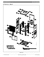
Страница 83: ...Spare Parts List 83 SM Series Heat Pump 6 720 220 406 2015 02 Revised 02 15 HZ Part List Cabinet Figure 130 6 720 220 429 01 ...

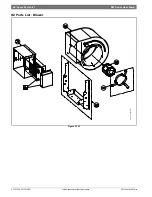
Страница 84: ...SM Series Heat Pump SM Series Heat Pump 6 720 220 406 2015 02 Subject to change without prior notice 84 Spare Parts List HZ Parts List Blower Figure 131 6 720 220 429 01 ...

Страница 85: ...Spare Parts List 85 SM Series Heat Pump 6 720 220 406 2015 02 Revised 02 15 HZ Parts List Refrigeration Figure 132 6 720 220 429 01 ...

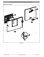
Страница 86: ...SM Series Heat Pump SM Series Heat Pump 6 720 220 406 2015 02 Subject to change without prior notice 86 Spare Parts List HZ Part List Panels Figure 133 6 720 220 429 01 ...

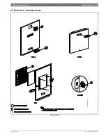
Страница 87: ...Spare Parts List 87 SM Series Heat Pump 6 720 220 406 2015 02 Revised 02 15 HZ Part List Detailed View Figure 134 6 720 220 429 01 ...

Страница 88: ...02666 8733802666 8733802666 8733802666 8733802666 26 Contactor Kit 8733802667 8733802667 8733802667 8733802667 8733802667 8733802667 8733802667 8733802667 8733802667 8733802667 27 Capacitor Kit 8733802668 8733802668 8733802759 8733802759 8733802760 8733802760 8733802761 8733802761 8733802761 8733802761 28 Transformer Kit 8733802669 8733802669 8733802669 8733802669 8733802669 8733802669 8733802669 ...

Страница 89: ...3802801 8733802801 83 20kW EH Fuse Box Kit 8733802802 8733802802 8733802802 8733802802 84 20kW EH Contactor Kit 8733802803 8733802803 8733802803 8733802803 85 HGRH ECM constant air flow Harness Kit 8733802714 8733802714 8733802714 8733802714 8733802714 8733802714 8733802714 8733802714 86 Water Piping Kit 8733803577 8733803577 8733803578 8733803578 8733803579 8733803579 8733803585 8733803585 873380...

Страница 90: ...SM Series Heat Pump SM Series Heat Pump 6 720 220 406 2015 02 Subject to change without prior notice 90 Spare Parts List Counter Flow Part List Cabinet Figure 135 6 720 220 430 00 ...

Страница 91: ...Spare Parts List 91 SM Series Heat Pump 6 720 220 406 2015 02 Revised 02 15 Counter Flow Part List Blower Figure 136 6 720 220 430 00 ...

Страница 92: ...SM Series Heat Pump SM Series Heat Pump 6 720 220 406 2015 02 Subject to change without prior notice 92 Spare Parts List Counter Flow Part List Panels Figure 137 6 720 220 430 00 ...

Страница 93: ...Spare Parts List 93 SM Series Heat Pump 6 720 220 406 2015 02 Revised 02 15 Counter Flow Part List Refrigeration Figure 138 6 720 220 430 00 ...

Страница 94: ...SM Series Heat Pump SM Series Heat Pump 6 720 220 406 2015 02 Subject to change without prior notice 94 Spare Parts List Counter Flow Part List Detailed View Figure 139 6 720 220 430 00 ...

Страница 95: ...Dimensional Drawings 95 SM Series Heat Pump 6 720 220 406 2015 02 Revised 02 15 DIMENSIONAL DRAWINGS Figure 140 ...

Страница 96: ...SM Series Heat Pump SM Series Heat Pump 6 720 220 406 2015 02 Subject to change without prior notice 96 Dimensional Drawings Horizontal Straight Through Figure 141 ...

Страница 97: ...Dimensional Drawings 97 SM Series Heat Pump 6 720 220 406 2015 02 Revised 02 15 Horizontal Hanging bracket location Figure 142 ...

Страница 98: ...SM Series Heat Pump SM Series Heat Pump 6 720 220 406 2015 02 Subject to change without prior notice 98 Dimensional Drawings COUNTER FLOW Figure 143 ...

Страница 99: ...Dimensional Drawings 99 SM Series Heat Pump 6 720 220 406 2015 02 Revised 02 15 CF VERTICAL Figure 144 ...

Страница 100: ...555 N W 65th Court Ft Lauderdale FL 33309 Phone 866 642 3198 Fax 954 776 5529 www bosch climate us Revised 02 15 ...

Отзывы: