Heat Recovery Package
|
41
SM Series Heat Pump
6 720 220 406 (2015/02)
Revised 02-15
Mode of operation Notes
1.
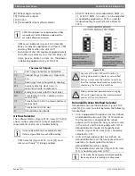
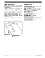
The Smart Start Assist has 2 indication LEDs on board.
The green LED indicates the status of the on-board power
supply while the red LED indicates an alarm condition or
the recovery time between starts.*
2. Once the main voltage is present, the green LED will be
fully ON. In case the main voltage is less than the stated
pickup voltage alarm value, the green LED will be flashing.
In case main voltage is higher than the stated pick-up
voltage and green LED is flashing, then this may indicate
that the on-board power supply is faulty. (Power Supply
Alarm)
3. Upon closing K1, the Smart Start Assist will start
ramping, duration of which is < 1 second, provided that the
minimum time from stop to start is respected. When
opening K1, the Smart Start Assist will stop without any
ramp down.
4. In the case of an under voltage, the Smart Start Assist
will shut down and the red LED flashes 2 times as long as
the under voltage is present. Once the main voltage is
restored the red LED will continue flashing for 5
minutes.Following these 5 minutes (6 minutes for HP
versions), the Smart Start Assist will start ramping function
in the case K1 is closed. The device can be reset at any
time by removing power on L1-N connection. When the
power is reapplied, the soft starter will star ramping up as
soon as K1 is closed, provided that the minimum time from
stop to start are respected.
5. If an over current (>80A for 1 sec.) is sensed, the Smart
start Assist will shut down and the red LED will flash 3
times indicating an over current situacion.This continues
for 5 minutes. In the case that the over current is still
present at the second attempt, user intervention is
required to reset the controller by cycling power for the
device to operate again as this implies that there are
problems in the system.
6. A detection circuitry provides protection in case of a
faulty starting capacitor EMR. In such situation, the red
LED will flash 4 times for 5 minutes. Smart Start Assist will
check the status of the starting capacitor EMR before
attempting a ramping function (in the case K1 is closed). If
at the second attempt, the starting capacitor EMR is found
to be faulty, user intervention is required to reset the
controller by cycling power for the device.
7. In the case of incomplete ramping of the Smart Start
Assist, the red LED will flash 5 times. The flashing will be
indicated by the red LED for 5 minutes. If after the second
attempt, there is another incomplete ramp alarm, user
intervention is required to reset the controller.
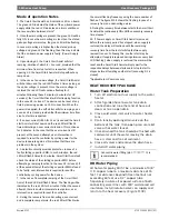
8. During the recovery from under-voltage, over-current
and incomplete ramp alarms, the red LED will flash twice
the normal flashing frequency using the same number of
flashes. The figure #108 shows the flashing in case of a
recovery from an under-voltage alarm.
9. During the recovery time between starts, the Smart Start
Assist will be continuously ON until the necessary recovery
time elapses.*
10. If Power supply on Smart Start Assist is removed
before the recovery period has elapsed, when supply is
restored, the delay will continue until the remaining
recovery time from the last start/stop (before supply
removal) is over. Following this, another start may be
attempted. If supply is removed during alarm recovery (red
LED flashing), when supply is restored, the alarm will be
reset and the Smart Start Assist will only wait for the
respective delays between starts and/or stop to start to
elapse before attempting another start (assuming K1 is
closed).
*Applicable to HP versions only
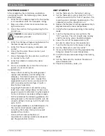
HEAT RECOVERY PACKAGE
Water Tank Preparation
1. Turn off electrical or fuel supply to the water
heater.
2. Attach garden hose to water tank drain
connection and run other end of hose out
doors or to an open drain.
3. Close cold water inlet valve to water heater
tank.
4. Drain tank by opening drain valve on the
bottom of the tank, then open pressure relief
valve or hot water faucet.
5. Once drained the tank should be flushed with
cold water until the water leaving the drain
hose is clear and free of sediment.
6. Close all valves and remove the drain hose.
7. Install HR water piping.
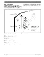
HR Water Piping
All hot water piping MUST be a minimum of 3/8”
O.D. copper tube to a maximum distance of 15
feet. For distances beyond fifteen feet but not
exceeding 60 feet use 1/2” copper tube.
Separately insulate all exposed surface of both
connecting water lines with 3/8” wall closed cell
insulation. Install isolation valves on supply and
return to the heat recovery. (Figure #109)
Concentric water fitting (p/n
8733907119
) is
recommended.

