Application Considerations
|
45
SM Series Heat Pump
6 720 220 406 (2015/02)
Revised 02-15
APPLICATION CONSIDERATIONS
Well Water Systems
Copper is adequate for ground water that is not
high in mineral content. Should your well driller
express concern regarding the quality of the well
water available or should any known hazards exist
in your area, we recommend proper testing to
assure the well water quality is suitable for use
with water source equipment. In conditions
anticipating moderate scale formation or in
brackish water a cupro-nickel heat exchanger is
recommended. In well water applications water
pressure must always be maintained in the heat
exchanger. This can be accomplished with either
control valve or a bladder type expansion tank.
When using a single water well to supply both
domestic water and the heat pump care must be
taken to insure that the well can provide sufficient
flow for both. In well water applications a slow
closing solenoid valve must be used to prevent
water hammer. Solenoid valves should be
connected across Y1 and C1 on the interface board
for all. Make sure that the VA draw of the valve
does not exceed the contact rating of the
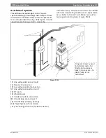
thermostat. (Figure #111)
Figure # 111 Example System Set-up
[1] Flex Duct Connection
[2] Low Voltage Control Connection
[3] Vibration Pad
[4] Ball Valves
[5] Solenoid Valve Slow Closing
[6] Condensate Drain Connection
[7] Drain Valves
[8] Hose Kits (optional)
[9] Pressure Tank (optional)
[10] P/T Ports (optional)
[11] Line Voltage Connection
[12] Electric Heater Line Voltage Disconnect
[13] Unit Line Voltage Disconnect
Cooling Tower/Boiler Systems
The cooling tower and boiler water loop
temperature is usually maintained between 50° F
to 100 ° F to assure adequate cooling and heating
performance.
In the cooling mode, heat is rejected from the unit
into the water loop. A cooling tower provides
evaporative cooling to the loop water thus
maintaining a constant supply temperature to the
unit. When utilizing open cooling towers, chemical
water treatment is mandatory to ensure the water
is free from corrosive elements. A secondary heat
exchanger (plate frame) between the unit and the
1
2
3
4
5
6
7
Typical Installation shown for
illustration purposes only.
9
8
10
11
12
13


