Cross-sections depend on
current consumption
use min. 4 mm².
For higher current consumption
24 VDC
A = Terminal block 4 mm²
B = Terminal block 10 mm²
Length max. 4 m
6 mm²
(blue)
0 V load
24 V load
Earth bar
X1S1
USV
L2
L3
10 mm² (green/yellow)
L1
PE
A
B
A
Power unit acc. to
EN 50178: SELV
Functional earth
PC
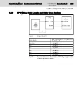
Required cross-sections and permitted
The permitted cable lengths are
PE
W1
N
V1
PE
PE
PE
U1
PE
L1
L2
L3
N
PE
PE
N
U2
PE
PE
N1
U2
L1.1
L2.1
L3.1
N
PE
e.g. drives
Transformer
6 mm² (green/yellow)
16 mm² (green/yellow)
min. 16 mm² (green/yellow)
all housing parts (functional earth)
to the device
to the housing of the control cabinet
PE neutral point
230V
400V
Fuses, better: protective motor switches
4 mm² (green/yellow)
16 mm² (green/yellow)
4 mm² (green/yellow
4 mm² (green/yellow)
230 V supply
leads
Overvoltage
Overvoltage
category III
Overvoltage category III
FE
N1
U2
PE
X1N1
X1S2
X10
Easily removable and visible
PE bars should be preferably installed on the mounting
plate. In the case of isolated PE bars both ends must
be connected to the mounting plate by means of copper
strips with a maximum length of 20 cm.
The cross-section of the copper strips has to be at least
equal to that of the incoming cable.
Overvoltage category I
Overvoltage
(3)
(1)
(1)
(2)
(3) An X1N1 is connected to an UPS that supplies several
= Terminals in isolated arrangement
category II
acc. to EN 60742
N conductor:
Use only with
permission of
the operator!
operator terminals
service plug receptacle(s)
cable lengths are specified in the
documentation of the connected
device (PC).
category II
specified in the chapter "UPS wiring"
several control cabinets with an uninterruptible power supply.
In this case also overvoltage category II applies.
(2)
10 mm² (green/yellow)
use 2 × 4 mm².
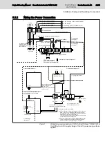
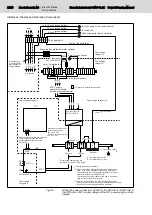
Fig.6-5:
Wiring the power connection: 24 VDC to the UPS and 115/230 VAC to
the UPS when 230 V supply voltage of the 24 V power supply unit are
applied
24/45
Bosch Rexroth AG | Electric Drives
and Controls
Rexroth IndraControl VAU 01.1Z | Project Planning Manual
Interfaces, Display and Operating Components
Содержание Rexroth IndraControl VAU 01.1Z
Страница 1: ...Electric Drives and Controls Pneumatics Service Linear Motion and Assembly Technologies Hydraulics ...
Страница 36: ...34 45 Bosch Rexroth AG Electric Drives and Controls Rexroth IndraControl VAU 01 1Z Project Planning Manual ...
Страница 38: ...36 45 Bosch Rexroth AG Electric Drives and Controls Rexroth IndraControl VAU 01 1Z Project Planning Manual ...
Страница 40: ...38 45 Bosch Rexroth AG Electric Drives and Controls Rexroth IndraControl VAU 01 1Z Project Planning Manual ...
Страница 44: ...42 45 Bosch Rexroth AG Electric Drives and Controls Rexroth IndraControl VAU 01 1Z Project Planning Manual ...
Страница 46: ...44 45 Bosch Rexroth AG Electric Drives and Controls Rexroth IndraControl VAU 01 1Z Project Planning Manual ...


