

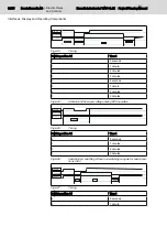


DSR / UPS -> PC AC power supply
unit OK
HIGH LEVEL
(+5 V)
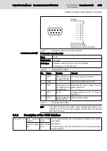
The DSR signal indicates whether the AC POWER SUPPLY UNIT is
ready. If the input voltage is not connected to the AC power supply unit
or if the AC power supply unit is defective, the red LED "Voltage Error
X1N1" is triggered.
AC power supply
unit is defective
or discharged
LOW LEVEL
(-5 V)
RTS / PC ->UPS PC OK
HIGH LEVEL
(+5 V)
The RTS signal indicates to the UPS, if the PC has booted. It is also
indicated, if
●
the PC is supplied with voltage via the UPS,
●
the COM interface is connected to the PC,
●
if the PC and the UPS software were started
PC not OK
LOW LEVEL
(-5 V)
DTR / PC -> UPS Stop of the AC
power supply unit
test
HIGH LEVEL
(+5 V)
The DTR signal starts the AC power supply unit test. For this, the RTS
signal must additionally have HIGH LEVEL. Independent of the signal
level of the DTR signal, a timer within the UPS switches off the internal
test load of 500 mA after max. 10 seconds if beforehand the AC power
supply unit test was started.
Start of the AC
power supply unit
test
LOW LEVEL
(-5 V)
Fig.6-12:
Description of the COM interface signals
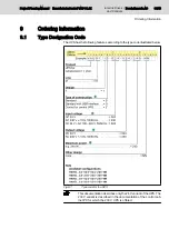
6.4
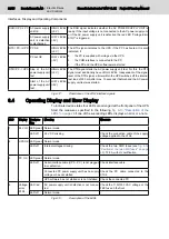
Operating Display and Error Display
To indicate device states four LEDs are arranged at the front panel of the UPS.
Start the measures specified in the following
if one of the succeeding LEDs displays an error or a note.
LED
Display Designa‐
tion
Meaning
Measure
1
24 V IN LED green Normal mode
-
LED off
24 V DC missing
Check the connection cable of the supply
voltage applied to the X1S2.
2
UPS OK LED green Normal mode
-
LED off
Internal voltages missing
Check the two SMD fuses (see
"Position of the two SMD fuses" on page
). T2.5 A with UL certification
3
PC OK LED green Normal mode
LED off
Serial interface cable (UPS – PC ) is not plugged
in or defective.
Check interface cable
Connected PC power supply unit has no supply
voltage or has not started
Check the PC cable connected to the
X1S2.
UPS software has not started or is not installed. Check the connected PC
4
Voltage
error
X1N1
LED red
AC power supply unit is defective or not connec‐
ted.
Check the 115V/230 VAC voltage or the
FKS fuse on the front
LED off
Normal mode.
-
Fig.6-13:
Description of the LEDs
28/45
Bosch Rexroth AG | Electric Drives
and Controls
Rexroth IndraControl VAU 01.1Z | Project Planning Manual
Interfaces, Display and Operating Components
Содержание Rexroth IndraControl VAU 01.1Z
Страница 1: ...Electric Drives and Controls Pneumatics Service Linear Motion and Assembly Technologies Hydraulics ...
Страница 36: ...34 45 Bosch Rexroth AG Electric Drives and Controls Rexroth IndraControl VAU 01 1Z Project Planning Manual ...
Страница 38: ...36 45 Bosch Rexroth AG Electric Drives and Controls Rexroth IndraControl VAU 01 1Z Project Planning Manual ...
Страница 40: ...38 45 Bosch Rexroth AG Electric Drives and Controls Rexroth IndraControl VAU 01 1Z Project Planning Manual ...
Страница 44: ...42 45 Bosch Rexroth AG Electric Drives and Controls Rexroth IndraControl VAU 01 1Z Project Planning Manual ...
Страница 46: ...44 45 Bosch Rexroth AG Electric Drives and Controls Rexroth IndraControl VAU 01 1Z Project Planning Manual ...