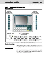
PLC function key
Address key
Address LEDs
S6
%I*.0.5
%Q*.0.5
S7
%I*.0.6
%Q*.0.6
S8
%I*.0.7
%Q*.0.7
S9
%I*.1.0
%Q*.1.0
S10
%I*.1.1
%Q*.1.1
S11
%I*.1.2
%Q*.1.2
S12
%I*.1.3
%Q*.1.3
S13
%I*.1.4
%Q*.1.4
S14
%I*.1.5
%Q*.1.5
Key switch left side (op‐
erator)
%I*.1.6
%Q*.1.6
Key switch right side
(Prog)
%I*.1.7
%Q*.1.7
Fig.4-10:
Addressing of the PLC function keys
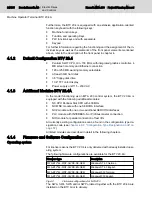
Two vacant logical addresses are to be assigned for inputs and outputs within
the PLC configuration.
4.2.6
Replacing the Slide-in Strips
General Information
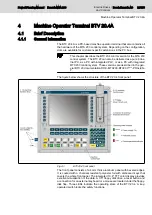
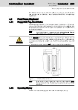
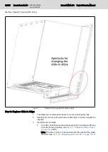
The 14 PLC function keys on the front of the BTV 20 can be labeled by using
a slide-in strip . The key row above the PLC function keys (OP2...OP9) is also
freely configurable using slide-in strips.
These strips, which are already inserted when the device is delivered, can be
freely replaced. Preprinted strips as well as a floppy-disk with templates are
also included in the scope of delivery so that you can create your own key
labels. How to replace the slide-in strips is decribed below.
Project Planning Manual | Rexroth MTA 200
Electric Drives
and Controls
| Bosch Rexroth AG
31/135
Machine Operator Terminal BTV 20.4A
Содержание Rexroth BTV 20.4A
Страница 1: ...Electric Drives and Controls Pneumatics Service Linear Motion and Assembly Technologies Hydraulics ...
Страница 12: ...10 135 Bosch Rexroth AG Electric Drives and Controls Rexroth MTA 200 Project Planning Manual ...
Страница 66: ...64 135 Bosch Rexroth AG Electric Drives and Controls Rexroth MTA 200 Project Planning Manual ...
Страница 134: ...132 135 Bosch Rexroth AG Electric Drives and Controls Rexroth MTA 200 Project Planning Manual ...
Страница 137: ...Notes Project Planning Manual Rexroth MTA 200 Electric Drives and Controls Bosch Rexroth AG 135 135 ...

