


English |
13
Bosch Power Tools
1 609 92A 1FM | (1.9.15)
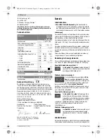
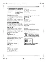
Technical Data
Declaration of Conformity
We declare under our sole responsibility that the product de-
scribed under “Technical Data” complies with all applicable
provisions of the directives 2011/65/EU, 1999/5/EC includ-
ing their amendments and is in conformity with the following
standards: EN 60335-1:2012, EN 60335-2-29:2004 +
A2:2010, EN 62311:2008-01, EN 300 330-2
V1.6.1:2015-03, EN 301 489-1 V1.9.2:2011-09, EN 301
489-3 V1.6.1:2013-08.
Technical documents at:
Robert Bosch GmbH, PT/ETM9,
70764 Leinfelden-Echterdingen, GERMANY
Robert Bosch GmbH, Power Tools Division
70764 Leinfelden-Echterdingen, GERMANY
Leinfelden, 24.08.2015
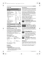
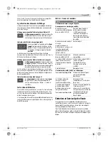
Operation
Starting Operation
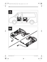
Observe the mains voltage!
The voltage of the power
supply must correspond with the data given on the name-
plate of the battery charger. Battery chargers marked with
230 V can also be operated with 220 V.
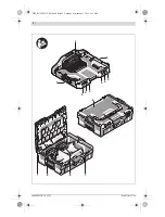
Charging Procedure
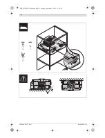
The charging process begins as soon as the mains plug of the
charger is plugged into the socket outlet, and the L-BOXX with
the inductive batteries is placed on the charging platform
1
.
The charging process only begins when the battery capacity is
less than 85 – 90 %. This prolongs the life of the battery.
Due to the intelligent charging method, the charging condi-
tion of the battery is automatically detected and the battery is
charged with the optimum charging current, depending on
battery temperature and voltage.
This gives longer life to the battery and always leaves it fully
charged when kept in the charger for storage.
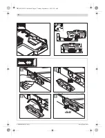
Meaning of the Indication Elements
Since two batteries can be charged independently of one an-
other, each battery has its own indicators.
Continuous Light Standby Indicator (green) 3
The
continuous light
of the
green
standby indi-
cator
3
shows that input voltage is present and
the charger is ready to use.
Flashing Charge Status Indicator 4
The fast charging process is indicated by
the
flashing
of the respective
green
LED of
the charge status indicator
4
. When the re-
spective share of the battery is charged, the
green flashing light changes to a
green continuous light
.
The battery can be removed at any time and used. When all
five LEDs indicate a green continuous light, the battery is fully
charged.
Continuous Light Error Indicator (red) 5
The
continuous light
of the
red
error indicator
5
shows that the temperature of the battery or
charger is outside of the permitted charging
temperature range, see section “Technical Da-
ta”. As soon as the permitted temperature range is reached,
the charger automatically switches to fast charging.
Flashing Error Indicator (red) 5
The
flashing light
of the
red
error indicator
5
signals a different fault of the charger, see sec-
tion “Troubleshooting – Causes and Corrective
Measures”.
Working Advice
With continuous or several repetitive charging cycles without
interruption, the charger can warm up. This is not meaningful
and does not indicate a technical defect of the battery charg-
er.
A significantly reduced working period after charging indi-
cates that the battery is used and must be replaced.
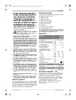
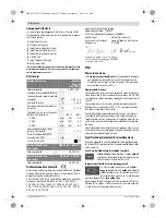
Battery Charger
Wireless
Charging
L-BOXX Bay
Article number
2 607 226 0..
Battery charging voltage
(automatic voltage detection)
V
10.8 –18
Charging current
A
2 x 3.0
Allowable charging temperature
range
°C
0 – 45
Charging time for battery
capacity, approx.
(80%)
100%
– 2.0 Ah
min
(35)
45
– 2.5 Ah
min
(45)
65
– 4.0 Ah
min
(65)
85
Number of battery cells
3 –10
Weight according to EPTA-
Procedure 01:2014
kg
3.1
Protection class
/
II
Battery pack
GBA 10,8 V …Ah OW-…
Article number
1 607 A35 ...
Battery pack
GBA 18 V …Ah MW-…
Article number
1 607 336 ...
Henk Becker
Executive Vice President
Engineering
Helmut Heinzelmann
Head of Product Certification
PT/ETM9
OBJ_BUCH-2572-001.book Page 13 Tuesday, September 1, 2015 9:31 AM