Bosch KBR16-3 Скачать руководство пользователя страница 66

66

 | 

Inspection and maintenance

Greenstar FS

6 720 810 590 (2015/05)

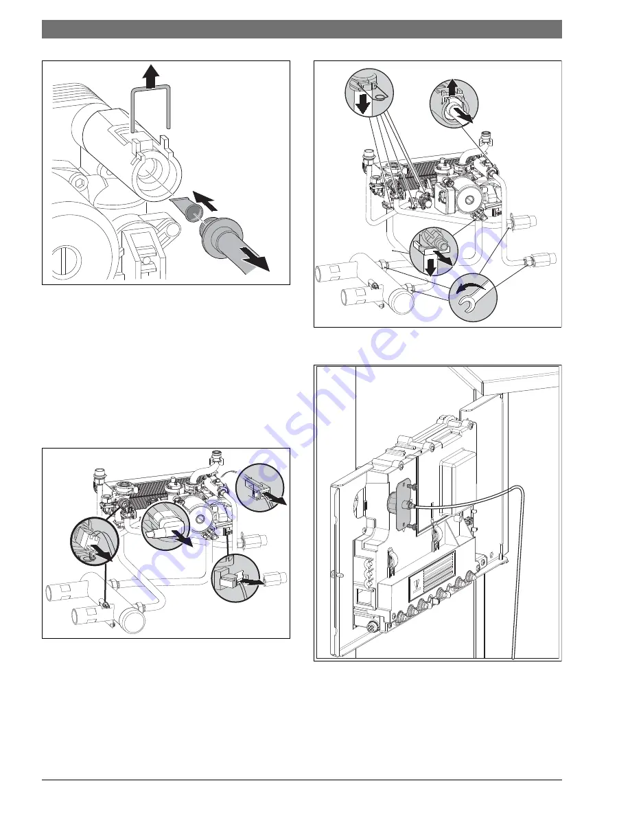
Fig. 77 Filter in fresh water pipe (combi boiler KWB.-3A only)

15.1.3 Plate type heat exchanger (only combi boiler KWB..-3A)

If the DHW output on the combi boiler is significantly reduced:
▶ Check filter in the cold water pipe for contamination (

Fig. 65).

▶ Depressurize the appliance.
▶ Remove the plate type heat exchanger and replace with a new unit.

-or-

▶ Descale with descaling agent approved for stainless steel (Grade 

316-1.4401).

To remove the plate type heat exchanger:
▶ Unplug electrical connections.
▶ Remove hose from safety relief valve.

Fig. 78 Unplugging electrical connections / removing hose from PRV

▶ Loosen/remove pipe connections.

Fig. 79 Removing pipe connections

▶ Remove the boiler pressure gauge from the Heatronic boiler control.

Fig. 80 Removing the boiler pressure gauge

▶ Loosen  the  quick  releases (steps 1 and 2) and remove the hydraulic 

assembly in its entirety (step 3).

6 720 641 933-92.1o

1

2

3

6720810590-41.1Wo

6720810590-42.1Wo

6720810590-32.1W

o

Содержание KBR16-3

Страница 1: ...technical documents that must be handed over to the owner or operator of the heating system Explain to the owner or operator how to use the heating system using the operating instructions Make sure that they are familiar with all required information for the safe and proper operation of the heating system NOTICE In Massachusetts this appliance must be installed by a licensed plumber or gas fitter ...

Страница 2: ...ansion vessel KWB 3A boiler only 31 6 3 KBR 3A appliances heating boilers Selecting an expansion vessel 32 6 4 Selecting the installation location 32 6 5 Low Loss Header LLH utilization 32 6 5 1 To utilize the LLH 32 6 6 Locating the appliance 33 6 6 1 Positioning the appliance 33 6 7 Installing a low water cut off LWCO 34 6 8 Connecting flue gas accessories 35 6 8 1 Installation of the exhaust an...

Страница 3: ...s 71 17 1 Troubleshooting 71 17 2 Faults that are shown on the display 72 17 3 Faults that are not shown on the display 74 17 4 Check sensor values 75 17 4 1 Outdoor temperature sensor 75 17 4 2 Additional supply temperature limiter 75 17 4 3 Supply temperature sensor External supply temperature sensor DHW tank temperature sensor DHW temperature sensor 75 17 5 Replacement code plug 75 18 Commissio...

Страница 4: ...em with the venting system or chimney which must be repaired immediately Ensurenoneoftheventpipesandchimneysaredamagedorblocked Connect only one appliance to each venting system or chimney The venting system must not feed into or route through another air extraction duct The venting system must be inspected annually All parts that show any signs of damage or corrosion must be replaced Never close ...

Страница 5: ...nnection of a LWCO 4 Gas conversion kit 5 DHW tank temperature sensor NTC 6 Flue adapter1 2 2 KWB Residential combi boiler for space heating and DHW generation Fig 2 Scope of delivery combi boiler KWB 3A Contents of package 1 1 Gas condensing boiler 2 Set of documents for appliance 3 Adapter for connection of a LWCO 4 Gas conversion kit 5 Flue adapter2 1 Concentric vent kit available as accessory ...

Страница 6: ...ligent boiler pump control Heatronic boiler control Three speed boiler circulator Automatic air vent combi boiler only Display Automatic ignition Continuously controlled output Full protection via the Heatronic with flame rod and solenoid valves No minimum circulating water flow rate required Suitable for all hydronic emitters Flue adapter for flue gas and combustion air with test ports Variable s...

Страница 7: ...clearances front rear side view 1 453 4 1163mm 2 4115 16 1065mm 3 279 16 700mm 4 24 600mm 5 7 7 8 200mm 6 23 4 70mm 7 4 102mm 8 4 102mm 9 41 1042mm 10 183 8 467mm 11 19 9 16 497mm Zero clearance from combustibles permitted but 4 102 mm recommended for serviceability 1 25mm Distance to door if mounted inside a closet with 24 600mm in front of boiler for serviceability M2 M1 M3 M4 M6 M8 M7 M9 M10 M1...

Страница 8: ...r FS 6 720 810 590 2015 05 3 7 Appliance layout heating boiler KBR 3A Fig 6 Appliance layout heating boiler KBR 3A 18 19 20 21 22 23 25 5 6 7 9 10 12 13 14 15 17 16 11 3 1 24 32 31 30 29 28 27 35 36 37 38 39 33 34 4 6720810590 35 1Wo 26 41 40 2 ...

Страница 9: ...s adjuster 13 Gas valve 14 Gas connection 15 Heating return connection 16 Heating supply connection 17 Low Loss Header with flow sensor 18 Fan 19 Electrode set 20 Primary heat sensor 21 Maximum safety sensor 22 Inspection and clean out cover 23 Condensate collector 24 Boiler circulator 25 Drain cock 26 Condensate trap 27 Heatronic boiler control 28 ON OFF switch 29 Burner on indicator 30 Service b...

Страница 10: ...20 810 590 2015 05 3 8 Appliance layout combi boiler KWB 3A Fig 7 Appliance layout combi boiler KWB 3A 22 23 24 25 26 27 30 28 31 7 8 9 10 11 12 14 15 17 18 19 21 20 16 13 3 4 5 1 29 38 37 36 35 34 33 41 42 43 44 45 39 40 6 6720810590 34 1Wo 32 47 46 2 ...

Страница 11: ... 15 Air vent 16 DHW thermostat 17 Gas valve 18 Gas connection 19 Central heat return connection 20 Central heating supply connection 21 Low Loss Header and flow sensor 22 Fan 23 Electrode set 24 Primary heat sensor 25 Maximum safety sensor 26 Inspection and clean out cover 27 Condensate collector 28 Flow meter 29 Pump 30 Three way valve 31 Drain cock 32 Condensate trap 33 Heatronic boiler control ...

Страница 12: ...3 9 Electrical wiring heating boiler KBR 3A Fig 8 Electrical wiring diagram heating boiler KBR 3A 6720810590 10 1Wo 1 T 2 5 4 3 6 LR LS N L NS 7 8 9 LP NP A F 1 2 4 B B 27 15 7 8 17 25 26 20 19 22 21 18 4 6 23 9 10 11 16 13 12 14 24 1 2 3 4 5 6 BUS TT out sen DHW sen LWCO ...

Страница 13: ...ing pump 10 DHW tank primary pump or 3 way valve 11 120 VAC connection 12 Empty future connectivity 13 DHS Sen Domestic Hot Water temperature sensor NTC 14 LWCO Low Water Cut Off 15 Out Sen Outdoor temperature sensor 16 BUS BUS connection to programmer 17 Low voltage Installer connection box 18 Ignition electrode 19 Boiler block temperature limiter 20 Boiler circulator 21 Flame rod electrode 22 LL...

Страница 14: ... 10 Electrical wiring combi boiler KWB 3A Fig 9 Electrical wiring diagram combi boiler KWB 3A 14 13 1 2 3 4 5 6 BUS TT out sen DHW sen LWCO 15 6720810590 09 1Wo 1 2 5 4 3 6 LR LS N L NS 7 8 9 LP NP A F 1 2 4 B B 28 7 24 26 27 22 18 19 17 21 20 16 4 6 6 23 25 9 8 10 11 12 T ...

Страница 15: ...ating pump 10 120 VAC connection 11 Empty future connectivity 12 LWCO Low Water Cut Of 13 Out Sen Outdoor temperature sensor 14 BUS BUS connection to programmer 15 Low voltage Installer connection box 16 Ignition electrode 17 Boiler block temperature limiter 18 Flow meter turbine 19 3 way valve space heating DHW heating 20 Flame rod electrode 21 LLH Supply temperature sensor 22 Boiler circulator 2...

Страница 16: ...PG Propane in W C mbar 8 13 19 9 32 3 Flue gas Flue gas mass flow at maximum minimum nominal output gps 6 8 1 7 6 7 2 6 Flue gas temperature 176 140 F 80 60 C at maximum minimum nominal heat input F C 136 133 58 56 136 133 58 56 Flue gas temperature 104 86 F 40 30 C at maximum minimum nominal heat input F C 99 88 37 31 99 88 37 31 CO2 at maximum nominal output 9 4 11 0 CO2 at minimum nominal outpu...

Страница 17: ... LPG Propane in W C mbar 8 13 19 9 32 3 Flue gas Flue gas mass flow at maximum minimum nominal output gps 9 4 3 2 9 2 4 8 Flue gas temperature 176 140 F 80 60 C at maximum minimumnominal heat input F C 145 133 63 56 145 133 63 56 Flue gas temperature 104 86 F 40 30 C at maximum minimum nominal heat input F C 115 90 46 32 115 90 46 32 CO2 at maximum nominal output 9 4 11 0 CO2 at minimum nominal ou...

Страница 18: ...LPG Propane in W C mbar 8 13 19 9 32 3 Flue gas Flue gas mass flow at maximum minimum nominal output gps 12 0 3 2 11 6 4 8 Flue gas temperature 176 140 F 80 60 C at maximum minimum nominal heat input F C 147 133 64 56 147 133 64 56 Flue gas temperature 104 86 F 40 30 C at maximum minimum nominal heat input F C 117 90 47 32 117 90 47 32 CO2 at maximum nominal output 9 4 11 0 CO2 at minimum nominal ...

Страница 19: ...26 1 LPG Propane in W C mbar 8 13 19 9 32 3 Flue gas Flue gas mass flow at maximum minimum nominal output gps 15 7 4 5 15 2 5 6 Flue gas temperature 176 140 F 80 60 C at maximum minimum nominal heat input F C 162 135 72 57 162 135 72 57 Flue gas temperature 104 86 F 40 30 C at maximum minimum nominal heat input F C 127 91 53 33 127 91 53 33 CO2 at maximum nominal output 9 4 11 0 CO2 at minimum nom...

Страница 20: ... 35 1 Max output rate 122 86 F 50 30 C BTU hr kW 114 125 33 5 119 625 35 1 Max output rate 176 140 F 80 60 C BTU hr kW 111 552 32 7 116 928 34 3 Gas connection value Natural gas Hs 1 010 BTU ft3 37 3 MJ m3 ft3 hr m3 h 149 4 2 Liquid Propane Gas HD S 2 500 BTU ft3 93 1 MJ m3 ft3 hr m3 h 59 1 7 Permissible gas inlet pressure NG in W C mbar 3 5 10 5 8 7 26 1 LPG Propane in W C mbar 8 13 19 9 32 3 Flu...

Страница 21: ...3 17 12 DHW Max DHW flow rate gpm l min 2 64 10 2 64 10 Nominal DHW flow rate at 140 F 60 C outlet temperature gpm l min 2 03 7 7 2 03 7 7 Outlet temperature F C 104 140 40 60 104 140 40 60 Max cold water inlet temperature F C 140 60 140 60 Max approved DHW pressure psi bar 150 10 3 150 10 3 Minimum water pressure psi bar 4 35 0 3 4 35 0 3 Flue gas Flue gas mass flow at maximum minimum nominal out...

Страница 22: ... 3 17 12 3 17 12 DHW Max DHW flow rate gpm l min 3 17 12 3 17 12 Nominal DHW flow rate at 140 F 60 C outlet temperature gpm l min 2 6 10 2 6 10 Outlet temperature F C 104 140 40 60 104 140 40 60 Max cold water inlet temperature F C 140 60 140 60 Max approved DHW pressure psi bar 150 10 3 150 10 3 Minimum water pressure psi bar 4 35 0 3 4 35 0 3 Flue gas Flue gas mass flow at maximum minimum nomina...

Страница 23: ...s Max input rate 180 79 F 82 26 C BTU hr kW 125 828 36 9 129 021 37 8 Max output rate 104 86 F 40 30 C BTU hr kW 114 125 33 5 119 625 35 1 Max output rate 122 86 F 50 30 C BTU hr kW 114 125 33 5 119 625 35 1 Max output rate 176 140 F 80 60 C BTU hr kW 111 552 32 7 116 928 34 3 Output rate domestic hot water DHW 113 F 45 C BTU hr kW 114 125 33 5 119 625 35 1 Output rate domestic hot water DHW 140 F...

Страница 24: ...eplacing an existing boiler it is important to checktheconditionoftheentirehotwaterdistributionsystemtoensure safe operation Common practice calls for inspecting an existing system initsentiretyandbringingituptocode Allpipeworkshouldbeproperly cleaned and flushed Voltage Vac 120 120 Frequency Hz 60 60 Max power consumption central heating mode W 205 205 Max power consumption standby mode W 6 6 Sou...

Страница 25: ... 8 feetabove grade directly in line with the exhaust vent terminal for the horizontally vented gas fueled heating appliance or equipment The signshallread inprintsizenolessthanone half inchinsize GAS VENT DIRECTLY BELOW KEEP CLEAR OF ALL OBSTRUCTIONS INSPECTION The state or local gas inspector of the side wall horizontally vented gas fueled equipment shall not approve the installation unless upon ...

Страница 26: ...rain Bleed point 17 Combination fast fill back flow preventer 18 Expansion tank vessel 5 1 1 To utilize the LLH Switch off and isolate the boiler Drain the boiler Remove front panel Locate the LLH at the left hand side of the lower section of the boiler 1 Unscrew the cap a from the body of the LLH c This will break the label across the cap and body indicating that the LLH has been employed 2 Withd...

Страница 27: ...4 PZ1 System pump 5 VZ1 VZ2 Zone valves 6 24V Transformer 7 CRC100 or CRC200 Zone 1 Comfort room controller 8 CRC100 or CRC200 Zone 2 Comfort room controller When using CZM100 and CRC100 or CRC200 controls the factory installed jumper at terminal 2e remains The LWCO jumper on terminal 2g is removed when using a LWCO For LWCO function an external transformer is required 6720810590 72 1Wo 1 2 BUS BU...

Страница 28: ...fast fill back flow preventer 17 Expansion tank vessel 5 2 1 To utilize the LLH Switch off and isolate the boiler Drain the boiler Remove front panel Locate the LLH at the left hand side of the lower section of the boiler 1 Unscrew the cap a from the body of the LLH c This will break the label across the cap and body indicating that the LLH has been employed 2 Withdraw the cap a and plunger assemb...

Страница 29: ...ger 100 4 PZ1 PZ2 Zone circulator pumps 5 CRC100 or CRC200 Zone 1 Comfort room controller 6 CRC100 or CRC200 Zone 2 Comfort room controller When using CZM100 and CRC100 or CRC200 controls the factory installed jumper at terminal 2e remains The LWCO jumper on terminal 2g is removed when using a LWCO For LWCO function an external transformer is required 1 2 BUS BUS 1 2 1 2 BUS BUS 1 2 24 V N L 120VA...

Страница 30: ... Convert open vented heating systems into closed systems Gravity heating systems Connect the appliance to the existing piping system via an external low loss header with a sludge separator refer to XXXX Galvanized radiators or pipes To prevent gas formation Do not use galvanized radiators or pipes Plastic pipe work If using plastic pipe work for the heating system eg underfloor radiant heating the...

Страница 31: ...protect the appliance against high pressure ANSI Z223 1 NFPA54 National fuel gas code or CAN CSA B 149 1 Natural Gas and Propane installation code Install a pressure regulator with a safety valve 6 1 2 Other important information The installation of this boiler must comply with all national and local code and regulations Only operate this boiler with the combined air flue system specifically desig...

Страница 32: ... Fig 18 Sample installation expansion vessel 6 4 Selecting the installation location Installation location requirements Observe the current national and local codes and regulations Observe country specific requirements Observe installation instructions of the venting system accessories and their clearances Combustion air To avoid corrosion keep the supply of combustion air free of corrosive substa...

Страница 33: ...theLLHplungermustbe removed to allow the hydraulic separation of the appliance from the system This allows the appliance to continue satisfying the demands of the heating system when high system flow rates are expected Fig 19 1 Central heating supply 2 Central heating return 3 Domestic hot water outlet 4 Domestic cold water inlet 5 Low Loss Header 6 5 1 To utilize the LLH Switch off and isolate th...

Страница 34: ...boiler in its final location Release the locknuts on the boiler feet Adjust the boiler feet until the boiler is level vertically and horizontally check using a spirit level Secure in position with the locknuts Fig 22 Levelling the boiler NOTICE Residue metal shavings and contaminants in the piping can damage the appliance Flush the piping thoroughly and completely to remove all residue Follow the ...

Страница 35: ... heating system circuit breaker Drain the boiler 1 Remove the safety clip from the dummy plug in the supply pipe 2 Pull off the dummy plug and place with the boiler documentation Ensure the O ring remains in place on the pipe Lubricate the O ring Fig 23 Installing a LWCO device removing dummy plug Screw the LWCO as far as possible into LWCO adapter located in the boiler accessory kit Follow the Hy...

Страница 36: ...test port 2 Flue gas test ports 3 Flue gas adapter 4 Vent flange Tighten the screws Using open venting Use basket on the air intake Using concentric venting system Fig 28 Horizontal venting system telescopic concentric vent kit 1 Intake 2 Exhaust L 2 feet to 3 feet 610 mm to 915 mm Install the concentric vent adaptor with the screws enclosed The twin pipe adaptor is supplied with the boiler kit as...

Страница 37: ...onnections Incorrectly fitted flue connections can lead to carbon monoxide escaping into the boiler room Ensure that the flue pipes and seals are not damaged Use only sealing compounds primer and glue approved with the vent material Never install a barometric or a thermally controlled vent damper with this boiler Connect only one boiler to each flue system Do not route the flue system piping throu...

Страница 38: ...ate available vent termination are certified as a part of the Greenstar Boiler The exhaust pipe must be properly supported and pitchedaminimumof inch 6 35 mm perfootbackto the boiler This allows the condensate to properly drain NOTICE Combustion air and vent pipe materials for KBR42 3A KWB42 3A Heat damage to 2 inch PVC pipes KBR42 3A KWB42 3A appliances combustion air and vent pipes use 2 inch CP...

Страница 39: ...bow Base Support SW to Flex Coupler M G Duravent PolyPro Centrotherm InnoFlue M G Duravent PolyPro Centrotherm InnoFlue 2PPS FCT ISCP02 2PPS SE90X ISBS0287 IFSFC02 Table 9 Roof terminals Wall terminals Flue System Materials Supplier Part number Ø 3 Ø 76 mm parallel stainless steel Flex L 46546901 90 elbow with inlet screen PVC elbow stainless steel screen IPEX elbow Langly Wire screen ULC S636 app...

Страница 40: ...ove forced air inlet Canada NOTICE Vent terminations must keep the following minimum clearances from electric meters gas meters regulators and relief equipment 4 feet 1220 mm Canada 1830 mm horizontally and in no case above and below unless a horizontal distance of 4 feet 1220 mm Canada 1830 mm is maintained NOTICE For clearances not specified in ANSI Z223 1 NFPA 54 or CSA B149 1 Clearanceinaccord...

Страница 41: ...supports every 5 feet 1525 mm of horizontal and vertical run beginning with support near boiler The condensate must be disposed of in accordance with applicable rules Periodic cleaning of the vent terminal and air intake screens is mandatory Avoid locating vent terminals near equipment or building features which can be subject to degradation from exhaust gases If multiple boilers are installed in ...

Страница 42: ... only Fig 38 Vertical venting system sealed combustion Key to Fig 36 Fig 37 and Fig 38 1 Intake 2 Exhaust 3 Concentric termination X Greater than 12 inches 305 mm Y 12 inches 305 mm above maximum snow level or at least 24 inches 610 mm whichever is greater 6 720 810 590 23 1W Y 1 2 6 720 810 590 24 1Wo 1 Y X 2 6 720 810 590 25 1Wo 1 2 Y X ...

Страница 43: ...d 13 depend on the installation situation the appliance type and the number of elbows used The transitions from rigid to corrugated pipe must conform to the S636 standard Plastic vent pipe for gas fired appliances 2 6 720 810 590 26 1Wo Y X 1 Y X X 6 720 806 922 08 2O 1 2 With Flex pipe the maximum length is reduced by 50 Flex pipe according to the suppliers instructions for use in the vertical pa...

Страница 44: ...PIPE Maximum effectivevent pipe length allowed for Ø 2 pipe Number of 90 elbows used KBR16 3 KBR21 3 KBR28 3 KWB28 3 KBR35 3 KWB35 3 KBR42 3 KWB42 3 1 66 ft 20 1 m 47 ft 14 3 m 2 61 ft 18 6 m 38 ft 11 6 m 3 56 ft 17 1 m 30 ft 9 1 m 4 51 ft 15 6 m 22 ft 6 7 m 5 46 ft 14 1 m 13 ft 4 0 m 6 41 ft 12 5 m 5 ft 1 5 m Table 13 Vent and combustion air pipe lengths with 2 diameter and the concentric termina...

Страница 45: ...e installation instructions of the accessory 7 2 Electrical connections in the junction boxes 7 2 1 Access to junction boxes All the electrical connections are available via the two installer junction boxes either high voltage 120 VAC and low voltage 24V DC Fig 42 Installer junction boxes with covers removed 1 High voltage junction box 2 Low voltage junction box 7 2 2 High voltage junction box The...

Страница 46: ...3 external heating pump page 59 7 2 4 DHW tank loading pump or 3 way valve with spring return only heating boiler KBR 3A The pump used must have the following connection values 120 VAC max 2 A Route cable from pump or 3 way valve to appliance Insert cable into the junction box as shown in Fig 47 Connect cable to the red plug according to Fig 46 Fig 46 Attach plug external DHW tank loading pump or ...

Страница 47: ...f Bosch controls see installation instructions for the Bosch control Connecting external manual reset high limit or low water cut off LWCO This connection allows the installation of external safety switches External manual reset high limit Low water cut off LWCO Radiant overheat protection Fig 50 Low voltage LV connections Fig 51 Low voltage LV terminals pre wire links not shown for simplicity 1 B...

Страница 48: ...ransformer near the boiler Follow LWCO manufacturer s instructions Connect the lead labeled BOILER GROUND green to pin 2 center Fig 48 2 of the white plug in the boiler junction box Connect the leads labeled 24V HOT red and24VCOMMON white to the external 24VAC transformer At the Low Voltage box on the rear of the boiler remove the link across LWCO connections and connect the leads labeled SWITCH C...

Страница 49: ...lve Bleed all air from the system Iftheboilerwaterpressurehasdropped filltheheatingsystemagain to 14 5 to 21 75 psi 1 to 1 5 bar On KBR 3A appliances heating boilers with a DHW tank open the cold water supply and open a DHW tap until water runs out Verifythatthegastypespecifiedontheratingplateisthesameasthe gas type used Open the gas cock 8 2 Switching the appliance ON OFF Startup Switch the appli...

Страница 50: ...ff at intervals for approx 4 minutes The display shows in alternation with the supply temperature If the display shows in alternation with the supply temperature the trap filling function is active page 59 Boiler high limit dial Typical supply temperatures Sample application 1 approx 95 F 35 C Frost protection 2 approx 109 F 43 C 3 approx 122 F 50 C Radiant floor heating system 4 approx 140 F 60 C...

Страница 51: ...ay should fill in Press the dial to confirm the setting Press menu button to return to main display 8 5 3 Setting type of heating system To open INSTALLER SETTINGS press and hold the menu button for approx 5 seconds System configuration will be highlighted Turn the dial one click counter clockwise to highlight Heating parameters Press the dial Heating circuit 1 will be highlighted Press the dial H...

Страница 52: ...eck flue path for tightness Check gas supply dynamic pressure page 64 Check that condensate is being discharged from the condensate hose If that is not the case switch the appliance first OFF and then ON again using the ON OFF switch That activates the trap filling sequence page 59 Repeat the procedure several times until condensate starts running out Complete commissioning report page 78 8 7 KBR ...

Страница 53: ...e the appliance switched ON set the boiler high limit to at least 95 F 35 C position 1 Tab 16 page 50 Fig 62 Frost protection of the heating system or If you want to leave the appliance switched OFF Mix Bosch approved anti freeze into the heating water Tab 5 page 31 and drain the DHW circuit Frost protection of the DHW tank Leave the appliance switched ON set the boiler high limit to at least 95 F...

Страница 54: ...nuous operation Turn DHW thermostat clockwise to max approx 158 F 70 C Fig 65 Thermal disinfection Wait until the maximum temperature has been reached Open all DHW taps from the nearest to the one furthest away and draw off hot water until it reaches a minimum of 158 F 70 C at all taps for at least 3 minutes Reset the DHW thermostat DHW recirculation pump and heating control to standard operation ...

Страница 55: ...pressure at speed 2 3 Residual head pressure at speed 3 default setting 4 Head pressure of the boiler pump by itself at speed 3 H Head pressure in feet of head m Circulating water volume in gallons per minute l h This function prevents the heating zone pump from seizing up following longer idle periods 0 2 5 7 8 1 4 3 6 15 20 25 10 5 0 H ft V gpm 1 2 3 4 400 800 1200 1600 200 600 1000 1400 7 0 6 5...

Страница 56: ...tton and key pad lock button simultaneously until the code 8 A appears second service level Onthesecondservicelevel selecttheservicefunction8 Eandvalue 00 The appliance restarts with the default settings 11 2 Overview of the service functions 11 2 1 First service level press and hold the service button until it lights up The unit automatically exits the service level if no button is pressed for 15...

Страница 57: ...ce function 1 F Pump mode only heating boiler KBR 3A Based on this setting the pump connected to the Heatronic or 3 way valve are controlled according to the configuration of the heating system The following settings are possible Pump mode 00 The appliance is used only as central heating boiler Pump mode 01 A 3 way valve for DHW tank loading is connected in boiler circuit before low loss header se...

Страница 58: ...ion 3 b Set anti cycle time Only if the automatic anti cycle time is disabled service function 3 A will this function be active The anti cycle time can be set from 00 to 15 0 to 15 minutes With 00 the anti cycle lock is switched off The shortest possible switching interval is 1 minute recommended for single zone or forced air heating systems Default setting is 03 Service function 3 C Switching dif...

Страница 59: ...ween summer and winter mode The next time there is a demand for heat in central heating or hot water mode the appliance is held at low output for 15 minutes The trap filling sequence remains active until the appliance has completed 15 minutes of operation at low output The display shows in alternationwiththe supply temperature The following settings are available 00 Condensate trap filling sequenc...

Страница 60: ...onic 02 External supply temperature sensor connected to IPM2 Default setting is 00 Service function 7 E Building drying function This service function allows you to start and stop the building drying function The following settings are available 00 Off 01 Heating operation only in accordance with the appliance or control setting i e all other heat demands are blocked Default setting is 00 Service ...

Страница 61: ...an may need to spin faster upon startup to ensure reliable ignition every time The start speed of the boiler fan can be set from 45 to 77 revolutions per second 1 s Default setting is 50 Service function 9 E Turbine signal delay only combi boiler KWB 3A Thisservicefunctionallowssettingatimedelaytopreventtheappliance starting up as a result of transient pressure spikes in the water supply Through s...

Страница 62: ...compensates for the effects of thin air and are therefore NOT derated up to 6000 feet 1829 m Above 6000 feet 1829 m a rate of 3 per 1000 feet 305 m applies Correction of the fan speed curve of the burner Use service function 0 d to adjust the elevation setting page 60 DANGER Personal injury and property damage This conversion shall only be performed by a trained and certified installer in accordan...

Страница 63: ...or maximum nominal output Briefly press the emissions test button The display shows the supply temperature in alternation with minimum nominal output Measure the CO2 or O2 level and the CO content of the flue gas Section 13 Remove the sealed screw Fig 74 3 from gas valve adjustment screw Fig 74 2 and set CO2 or O2 level for minimum nominal output Fig 74 Set CO2 or O2 level for minimum nominal outp...

Страница 64: ... output Minimum nominal output 13 2 Measuring CO content of flue gas Use a multiport flue gas probe for the measurements Open one of the flue gas test ports Fig 71 Insert the flue gas probe approx 2 3 4 inches 70 mm into the test port and seal around it Press the emissions test button to select maximum nominal output Measure the CO levels Repeatedly press the emissions test button until the light ...

Страница 65: ...ittings HFt 1 v 5 part 8 709 918 010 0 Use part 8 719 918 658 0 as heat conducting paste Use only genuine Bosch spare parts Request spare parts Section 19 page 80 Replace removed gaskets and O rings with new ones After the inspection maintenance Re tighten all loosened threaded connections Restart the appliance page 49 Check all connections for leaks Check the gas air ratio and adjust if necessary...

Страница 66: ... or Descale with descaling agent approved for stainless steel Grade 316 1 4401 To remove the plate type heat exchanger Unplug electrical connections Remove hose from safety relief valve Fig 78 Unplugging electrical connections removing hose from PRV Loosen remove pipe connections Fig 79 Removing pipe connections Remove the boiler pressure gauge from the Heatronic boiler control Fig 80 Removing the...

Страница 67: ... electrodes Remove the electrode set page 8 10 including gasket and check the electrodes for contamination clean or replace as required Re install electrode set with new gaskets and check for leaks Fig 83 Reinstalling the electrode set Fig 84 Check for gas leaks 15 1 5 Burner servicing Remove the burner cover steps 1 4 Fig 85 Removing the burner cover 1 3 2 6720810590 43 1Wo 1 6 720 641 933 50 2O ...

Страница 68: ...nger gaskets the heat exchanger brush and the heat exchanger cleaning blade which are available as spare parts Remove the condensate trap steps 1 and 2 and place a suitable container underneath Fig 87 Removing the condensate trap With the cleaning blade clean the heat exchanger block from the bottom to the top Fig 88 Cleaning the heat exchanger with the cleaning blade NOTICE Damage to the coating ...

Страница 69: ...Fig 91 Cleaning the condensate tray Rinse the heat exchanger with water from the top Clean the condensate trap connection Close the inspection opening again using a new gasket and tighten the screws with approx 3 69 ft lbf 5 Nm 15 1 7 Condensate trap cleaning Remove the condensate trap steps 1 and2 and check that the heat exchanger has a clear passage Fig 92 Removing the condensate trap Remove and...

Страница 70: ...tem flush and refill with fresh water to prevent system damage or leaks If the fill water does not meet the requirements of page 30 treat the water to bring it within the permissible range If antifreeze is being used in the system check the frost protection properties to ensure the site specific requirements are met 15 1 12 Inspecting electrical wiring Checkelectricalwiringformechanicaldamageandre...

Страница 71: ...page 64 inches W C mbar 5 Gas air ratio at min max nominal output page 63 min max 6 Gas and water side leak test page 44 7 Inspect electrodes page 67 8 Inspect heat exchanger block page 68 9 Check burner page 67 10 Inspect diaphragm in mixer unit page 70 11 Clean condensate trap page 69 12 With the system depressurized check the expansion vessel pre charge pressure vs the static head of the heatin...

Страница 72: ...e than 3 seconds Save function The display shows the supplytemperatureinalternation with The appliance works for 15 minutes at the minimum nominal output service function 2 F The display shows the supplytemperatureinalternation with The appliance works with the set maximum output in heating mode service function 1 A The display shows the supplytemperatureinalternation with The appliance works for ...

Страница 73: ...ordance with the commissioning report page 78 DANGER Explosion Close the gas cock prior to working on the gas train Checkforgasleaksaftercarryingoutworkonthegas train DANGER Risk of flue gas poisoning Checkforleaksaftercarryingoutworkontheventing system DANGER Risk of electric shock Always disconnect the appliance from the mains power before performing any work Disconnect the emergency shutoff swi...

Страница 74: ...d out Check temperature sensor and leads for interruptions or shorts and replace if defective Temperature guard TB1 has tripped Check if jumper across 8 9 or PR P0 is missing Reset external temperature limiter if installed Reset LWCO if installed d5 External supply temperature sensor defective low loss header The external supply temperature sensor was recognized on the BUS and then reconnected to ...

Страница 75: ...and ignition leads replace PCB if defective Check gas air ratio correct if out of specification F1 Internal data error Reset boiler to the factory default setting service function 8 E F7 Flame detected even when burner is off Check electrodes replace if defective Check flue gas system clean or repair if defective Check PCB for moisture dry if needed FA After switching gas off Flame is detected Che...

Страница 76: ...lectrodes for visual damage replace if defective Check flue gas system clean or repair if defective Check gas air ratio replace gas valve if defective Check gas valve replace if defective Check burner replace if required DHW has unpleasant odor or has a dark color Perform thermal disinfection of the DHW circuit Replace sacrificial anode in the tank if installed Consult local water department Set s...

Страница 77: ...4 90 1 177 212 100 886 Table 32 Resistance table supply temperature limiter Temperature F C Testing tolerance 10 Resistance Ω 68 20 14 772 77 25 11 981 86 30 9 786 95 35 8 047 104 40 6 653 113 45 5 523 122 50 4 608 131 55 3 856 140 60 3 243 149 65 2 744 158 70 2 332 167 75 1 990 176 80 1 704 185 85 1 464 194 90 1 262 203 95 1 093 212 100 950 Table 33 Resistance table NTCs Appliance Order number KB...

Страница 78: ...r pressure operation Gas setting and flue gas test Gas conversion NG LPG propane Inlet gas pressure W C mbar Gas static supply pressure W C mbar Selected maximum output MBH kW Selected minimum output MBH kW Gas flow rate at maximum nominal output gpm l min Gas flow rate at minimum nominal output gpm l min Net calorific value HiB per gas supplier MBTU ft3 kWh m3 CO2 at max nominal output CO2 at min...

Страница 79: ... out Tightness test carried out on the gas and water sides Commissioning includes checking the settings a visual heating leak test and a functional check of the boiler and control The system installer conducts a test of the heating system This system has been checked to the extent described ___________________________________________________________ Name of service installing contractor The docume...

Страница 80: ...KWB28 3 KWB35 3 KWB42 3 Spare parts list Group 1 Sheet metal page 82 Group 2 Burner Heat exchanger page 84 Group 3 Gas valve page 86 Group 4 Pipes combi boiler KWB 3A page 88 Group 5 Pipes heating boiler KBR 3A page 90 Group 6 Control box page 92 Group 7 Hydraulic block combi boiler KWB 3A page 94 Group 8 Accessories for service installation page 94 Table 35 Spare part groups Greenstar ...

Страница 81: ...Spare parts 81 6 720 810 590 2015 05 Greenstar FS Fig 94 Group 1 Sheet metal Greenstar 6720810590 73 1Wo ...

Страница 82: ...5 407 328 0 11 Shape screw 8 713 407 021 0 12 Washer 80mm 8 711 004 232 0 13 Resonator 8 716 117 337 14 Adaptor 8 716 117 334 16 Silencer 8 710 725 353 0 17 Seal 8 711 004 278 0 18 Throttle disc 8 7 10 100 209 0 19 Screw M5 x 20mm 8 716 117 397 20 Seal 8 716 117 487 21 Damper 2x 8 713 204 016 0 22 Assembly junction box cover 8 716 117 488 24 Screw 10x 2 910 611 424 0 26 Case inner door 8 716 117 4...

Страница 83: ...Spare parts 83 6 720 810 590 2015 05 Greenstar FS Fig 95 Group 2 Burner Heat exchanger Greenstar 21 20 19 31 15 16 14 13 12 8 11 5 9 36 10 23 3 2 4 3 6 7 1 9 16 19 4 24 33 33 17 6720810590 74 3Wo ...

Страница 84: ... 331 8 Cover 8 711 000 262 0 9 Sealing 8 710 103 153 0 10 Shield 8 718 003 836 0 11 Clip 10x 8 710 100 190 0 12 Set of electrodes 8 718 107 089 0 13 Inspection window 8 715 600 018 0 14 Washer 10x 8 711 004 264 0 15 Burner 8 718 006 658 0 16 Burner sealing 8 711 004 168 0 17 Cover 8 715 406 318 0 17 Cover 8 715 416 029 0 18 Fixing set 8 710 305 296 0 19 Seal 8 711 004 146 0 20 Bracket fan 8 716 11...

Страница 85: ...Spare parts 85 6 720 810 590 2015 05 Greenstar FS Fig 96 Group 3 Gas valve Greenstar 6720810590 75 1Wo ...

Страница 86: ...balance tube 8 718 221 063 0 11 Gas pipe top USA 8 718 225 762 0 13 Gas pipe 8 710 735 387 0 14 Lead seal 8 716 117 348 16 Washer 8 729 000 183 0 17 Fan RG128 USA 8 718 226 184 0 18 O ring 10x 8 722 880 175 0 19 Screw M4 x 8mm taptite zc pl p h 2 914 411 412 0 20 Air limiter 8 710 505 210 0 20 Air limiter 8 710 505 212 0 20 Air limiter 8 716 117 452 21 Connecting flange 8 710 506 279 0 22 Nipple U...

Страница 87: ...ar FS Fig 97 Group 4 Pipes combi boiler KWB 3A Greenstar 12 28 21 11 11 9 29 37 32 24 25 1 41 26 2 35 42 30 15 11 20 15 14 31 38 7 17 38 27 36 18 7 31 11 19 34 27 23 22 33 33 8 34 5 7 10 11 12 13 10 Item 39 Flow sensor not shown 6720810590 76 2Wo ...

Страница 88: ...7 518 20 Pipe CH flow 8 716 117 519 21 Elbow flow pipe 8 716 106 499 0 22 Pressure gauge USA 8 716 117 503 23 O ring 2 62 x 6 02 ID EPDM 10x 8 716 140 810 0 24 Upper rear pipe 8 716 117 511 25 O ring 26 34 x 5 33 5x 8 710 205 098 0 26 Washer set 8 710 103 154 0 27 O ring 13 87 x 3 5 L 10x 8 716 107 439 0 28 Cap closing connection 8 716 117 508 29 Temperature sensor 8 714 500 117 0 30 Assembly LLH ...

Страница 89: ...0 590 2015 05 Greenstar FS Fig 98 Group 5 Pipes heating boiler KBR 3A Greenstar 28 38 33 29 25 29 9 8 31 36 41 30 5 6 7 2 24 31 32 10 11 15 1 9 40 23 13 9 12 18 22 19 9 9 34 14 Item 37 Flow sensor not shown 6720810590 77 2Wo ...

Страница 90: ...psi 8 718 226 180 0 15 Expansion vessel plug 8 716 117 898 18 Pump KBR USA 8 718 226 172 0 19 Return pipe 8 710 735 450 0 22 Plug 8 713 301 152 0 23 O ring 26 34 x 5 33 5x 8 710 205 098 0 24 Washer set 8 710 103 154 0 25 Temperature sensor 8 714 500 117 0 28 Cap closing connection 8 716 117 508 29 O ring 17 x 4 5x 8 710 205 085 0 30 Assembly LLH 8 716 117 509 31 Washer 23 9 x 17 2 x 1 5 1x 8 716 1...

Страница 91: ...Spare parts 91 6 720 810 590 2015 05 Greenstar FS Fig 99 Group 6 Control box Greenstar 6720810590 78 1Wo ...

Страница 92: ...714 432 520 0 Code plug 2521 LPG 31 8 714 432 521 0 Code plug 2524 NG 23 8 714 432 524 0 Code plug 2525 LPG 31 8 714 432 525 0 Code plug 2528 NG 23 8 714 432 528 0 Code plug 2529 LPG 31 8 714 432 529 0 11 Cover 8 737 702 329 0 12 Grommet 10x 8 710 506 185 0 16 Earth harness 8 716 117 523 17 Harness low voltage appliance 8 716 117 524 20 Fuse 8 744 503 045 0 21 Harness accessories 8 716 117 525 22 ...

Страница 93: ...Spare parts 93 6 720 810 590 2015 05 Greenstar FS Fig 100 Group 7 Hydraulic block combi boiler KWB 3A Greenstar 6720810590 79 1Wo ...

Страница 94: ...7 Drain valve 8 716 771 432 0 28 Expansion vessel plug 8 716 117 507 29 O ring 13 87 x 3 53 L 10x 8 716 107 439 0 30 Safety clip inlet adapter 8 716 106 432 0 31 Diverter valve assembly 8 716 106 845 0 32 Diverter valve assembly motor 8 716 106 847 0 33 Screw M5 stainless 8 716 106 848 0 34 Flow turbine adapter 8 716 106 433 0 35 Flow sensor 8 737 600 781 0 37 O ring 22 x 3 L 8 716 117 069 38 Flow...

Страница 95: ... Connecting LWCO device 48 Connecting power supply 47 DHW circulation pump 46 Tank primary pump KBR only 46 Electrical wiring KBR 3A 12 KWB 3A 14 Energy saving 50 Environmental responsibility 65 Expansion vessel 70 F Factory settings 52 Fault codes 73 Faults 73 Not shown on the display 76 Shown on the display 74 First service level 57 Flue gas accessories 36 Frost protection 53 Fuses 12 14 45 G Ga...

Страница 96: ...i cycle time service function 3 b 58 Appliance type service function 4 E 59 Audible warning tone service function 4 d 59 Bleeding function service function 2 C 58 Building drying function service function 7 E 60 Code plug number service function 3 b 61 Condensate trap filling sequence service function 4 F 59 Connecting an external supply temperature sensor service function 7 d 60 Constant mode ser...

Страница 97: ...ce function 6 C 60 Switching differential service function 3 C 58 Temperature at tank temperature sensor service function A C 61 Turbine signal delay only KWB 3A service function 9 E 61 Voltage terminal 2 service function 6 b 60 Service level First service level 57 Second service level 60 Set functionality of black plug connection NZ LZ 59 Settings Changing sensor curve of the heating pump 55 Shut...

Страница 98: ...98 Greenstar FS 6 720 810 590 2015 05 Notes ...

Страница 99: ... 99 6 720 810 590 2015 05 Greenstar FS Notes ...

Страница 100: ...l 603 552 1100 Fax 603 965 7581 www bosch climate us U S A Products manufactured by Worcester Bosch Group Cotswold Way Worcester WR4 9SW www worcester bosch co uk Bosch Thermotechnology Corp reserves the right to make changes without notice due to continuing engineering and technological advances ...

Отзывы: