www.blaubergventilatoren.de
11
VENTO A50 / A50-1 / A50 S / A50-1 S
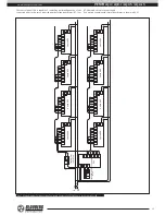
Connection of the unit in compliance with the wiring diagram in fig. 19
enables synchronous connection of up to 4 units. In this very case the 12 W
power transformer AT-12 is used.
Power supply 230 V / 50 Hz (or 120 V / 60 Hz) must be connected both to the
control panel SEA (SEA-Т) and to each ventilation unit to enable actuation of
the automatic shutters (socket connectors 31-32 in each case).
The inputs on the controller socket connectors are marked 21 to 25. The
outputs on the controller socket connectors are marked 11 to 15.
The socket connectors of the connecting cable supplied with the unit are
marked 1 to 5 and must be connected to the controller socket connectors
marked 11-15 for outputs or 21-25 for inputs.
Cable channel B:1. Vento A50
Cable channel A:1. Vento A50
Cable channel B:N. Vento A50
Cable channel A:N. Vento A50
SEA control panel
~120 V
or
~230 V
~120 В
или
~230 В
~120 V
or
~230 V
~120 V
or
~230 V
~120 V
or
~230 V
~120 V
or
~230 V
white
white
red
red
grey
brown
yellow
green
white
grey
brown
yellow
green
white
gre
y
br
own
yello
w
gr
een
whit
e
gre
y
br
own
yello
w
gr
een
whit
e
gre
y
br
own
yello
w
gr
een
whit
e
gre
y
br
own
yello
w
gr
een
whit
e
gre
y
br
own
yello
w
gr
een
whit
e
gre
y
br
own
yello
w
gr
een
whit
e
Transformer 12 W
АТ-12
Fig. 19. General wiring diagram for connection of up to 4 Vento A50 units to a single SEA control panel

