www.blaubergventilatoren.de
13
VENTO A50 / A50-1 / A50 S / A50-1 S
15
14
13
12
11
15
14
13
12
11
32
31
34
33
36
35
Control panel
SEA
Transformer 12W
AT-12
Transformer 12W AT-12
~12
V
230
V
25
24
23
22
21
15
14
13
12
11
31
Vento A50
N
L
32
Flow Out
Flow
In
25
24
23
22
21
15
14
13
12
11
31
32
25
24
23
22
21
15
14
13
12
11
31
32
25
24
23
22
21
15
14
13
12
11
31
32
25
24
23
22
21
15
14
13
12
11
31
Vento A50
32
25
24
23
22
21
15
14
13
12
11
31
32
25
24
23
22
21
15
14
13
12
11
31
32
25
24
23
22
21
15
14
13
12
11
31
32
Vento A5
0V
ento A5
0V
ento A5
0
Vento A5
0V
ento A5
0V
ento A5
0
Flow Out
Flow
In
Flow Out
Flow
In
Flow Ou
t
Flow
In
Flow Ou
t
Flow
In
Flow Out
Flow
In
Flow Out
Flow
In
Flow Out
Flow
In
JMP
1J
MP1
JMP1
JMP1
JMP1
JMP1
JMP1
JMP
1
~12
V
230
V
yello
w
green
white
grey
brow
n
yello
w
green
white
1 grey
2 brown
3 yellow
4 green
5 white
1 grey
2 brown
3 yellow
4 green
5 white
1 grey
2 brown
3 yellow
4 green
5 white
1 grey
2 brown
3 yellow
4 green
5 white
1 grey
2 brown
3 yellow
4 green
5 white
1 grey
2 brown
3 yellow
4 green
5 white
1 grey
2 brown
3 yellow
4 green
5 white
1 grey
2 brown
3 yellow
4 green
5 white
1 grey
2 brown
3 yellow
4 green
5 white
1 grey
2 brown
3 yellow
4 green
5 white
1 grey
2 brown
3 yellow
4 green
5 white
1 grey
2 brown
3 yellow
4 green
5 white
1 grey
2 brown
3 yellow
4 green
5 white
1 grey
2 brown
3 yellow
4 green
5 white
1 grey
2 brown
3 yellow
4 green
5 white
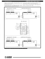
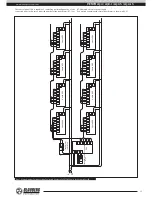
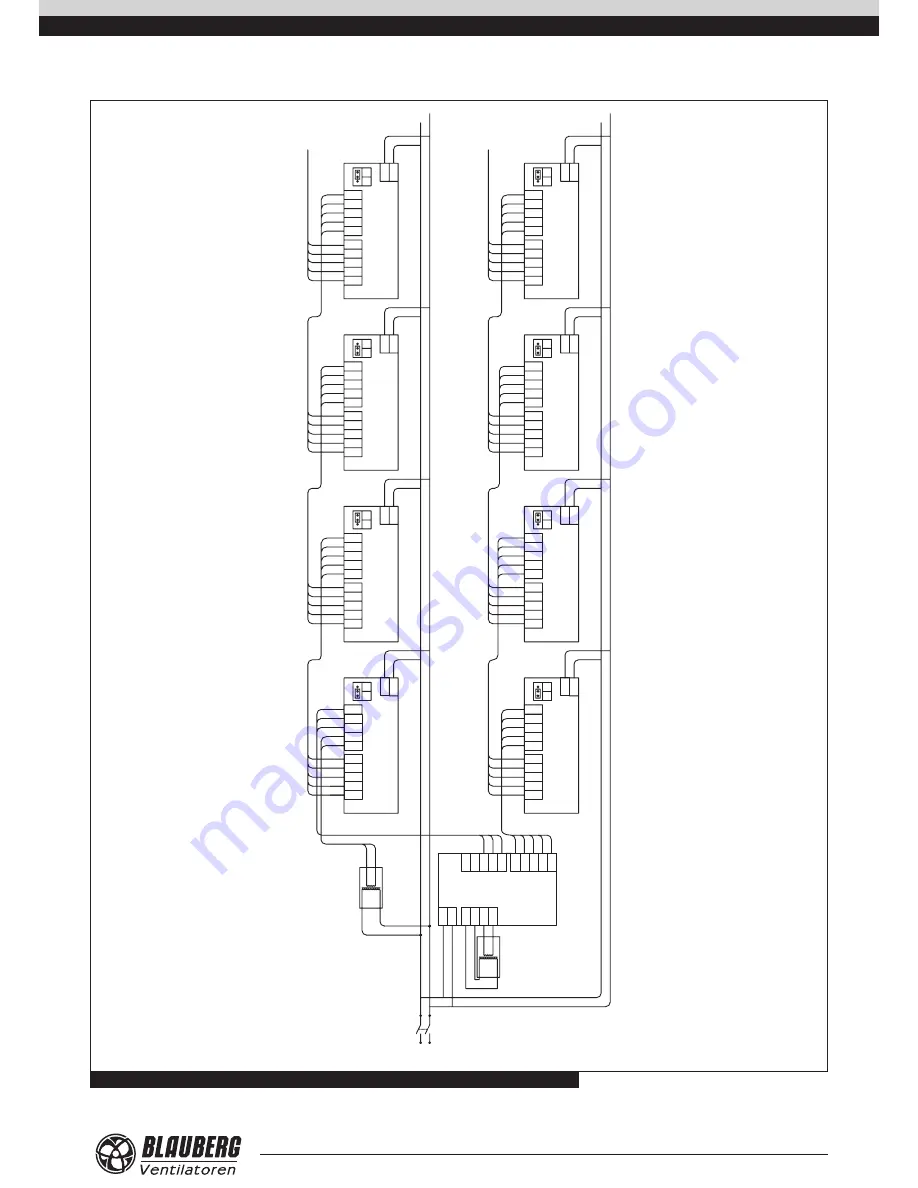
Fig. 21. Wiring diagram for connection of unlimited number of VENTO A50 units to the controller SEA
The control panel SEA is capable of controlling unlimited quantity of the
connected units. In this case a required number of the transformers AT-12 or
AT-40 must be used for power supply.
Connection example with several transformers is shown in fig. 21.

