


www.blaubergventilatoren.de
7
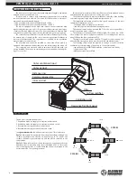
VENTO A50 / A50-1 / A50 S / A50-1 S
5.
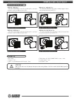
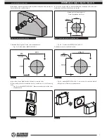
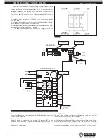
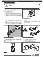
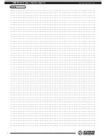
Install the ceramic regenerator with both filters, front and back, and the air
flow rectifier in this sequence, fig. 9.
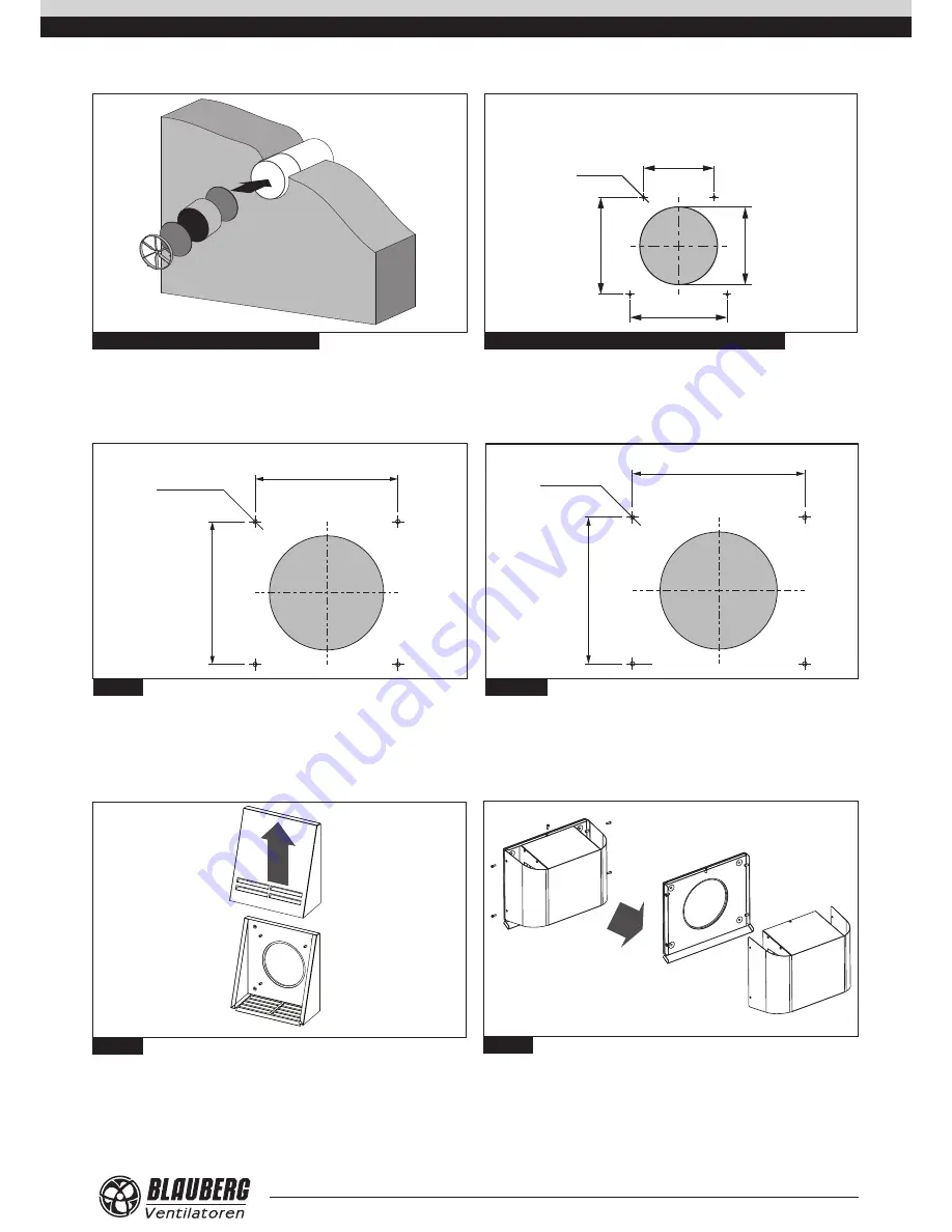
6.
Insert the dowels 5x25 in the wall and fix the ventilation unit to the wall
with screws 3x25 from the delivery set, fig. 10.
Fig. 9. Unit components mounting
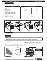
Fig. 10. Hole marking for the ventilation unit
Marking of the fastening holes
for the ventilation unit, mm
195
Ø6
4 holes
150
196
170
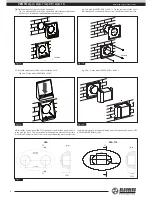
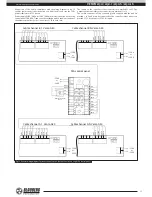
7.
Mark the fastening holes for the outer ventilation hood:
•
Fig. 11a − for the models VENTO A50 / A50-1;
•
Fig. 11b − for the models VENTO A50 S / A50-1 S.
Drill 40 mm holes for the dowels 6x40.
Fig. 11а.
Fig. 11b.
193,5
Ø6
4 holes
246,4
220
Ø6
4 holes
220
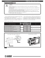
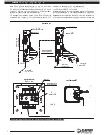
8.
Insert the dowels 6x40 from the delivery set into the holes.
9.
Disassemble the outer ventilation hood to enable access to the fastening
holes:
•
Fig. 12a - models VENTO A50 / A50-1. Remove the upper part of the outer
ventilation hood.
•
Fig. 12b - models VENTO A50 S / A50-1 S. Loosen these 5 screws and take off
the upper part of the outer ventilation hood.
Fig. 12а.
Fig. 12b.


