background image

4

www.blaubergventilatoren.de

VENTO A50 / A50-1 / A50 S / A50-1 S

DESIGN AND OPERATING LOGIC

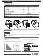
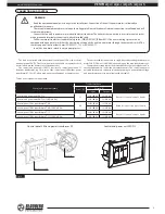
The unit consists of a telescopic duct with adjustable length,  a ventilation 

unit and an outer ventilation hood. 

Two filters and a ceramic heat accumulator (regenerator) are installed 

inside of the telescopic air duct. The round Ø 150 mm air duct is made of 

plastic and has an adjustable length:

– 240 up to 460 mm for the models VENTO A50 / A50-1;

– 120 up to 420 mm for the models VENTO A50 S / A50-1 S.

The unit is equipped with a high-tech ceramic heat accumulator with 

regenerating efficiency up to 91%. Due to the cellular structure is has larger 

contact surface and higher efficiency. The heat accumulator is featured with 

excellent heat-conducting properties and thermal energy storage capacity. 

The ceramic heat accumulator is used for extract air heat energy recovery 

for warming up of supply air. The cord inside the regenerator facilitates its 

removal for maintenance. The regenerator is installed on the insulation 

material used as a sealer as well.  

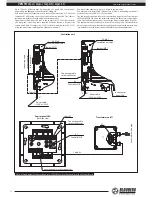
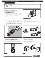
The ventilation unit must be installed on inner side of the wall. It is 

equipped with automatic shutters that close the air duct when the unit is off. 

Air is supplied and extracted with an axial reversible EC-fan with low 

energy demand. The motor has overheating protection and ball bearings for 

longer service life. 

Two built-in filters with total filter class G3 are used for supply and extract 

air filtration and the regenerator anti-soiling protection. 

The outer ventilation hood must be installed on outer side of the building 

to prevent ingress of large objects and water into the unit. 

The integrated automation enables two-speed operation of the unit 

(minimum or maximum speed): 

– ventilation mode (air supply or air extract);

– reversible operation mode with heat regeneration. 

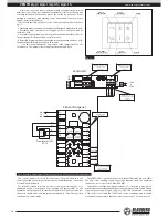
The external control and power unit SEA-T12 or the control panel SEA is 

used for operation mode control. 

The delivery set of the units VENTO A50 Pro / A50-1 Pro / A50 S Pro / A50-1 

S Pro includes the control and power unit SEA-T12 consisting of the control 

panel SEA and the 12W transformer AT-12. 

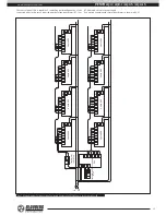
The single control and power unit SEA-T12 enables connection up to 4 

units and their integration into a central controlled ventilation system. 

The following components are required to arrange a central controlled 

ventilation system consisting of from 4 up to 12 ventilation units: 

– required number of VENTO A50 units (no control unit is included); 

– control panel SEA; 

– 40W power transformer AT-40.

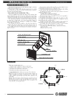
Outer ventilation hood
Outer air duct 

Inner air duct

Ceramic regenerator

Distance ring

Filter 

Filter 

Air flow rectifier 

Ventilation unit

Decorative flat front panel

Fig. 1. Unit design 

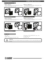
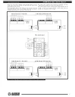
The unit has four ventilation modes:
1. Ventilation mode (air supply or air extract) at first speed.
2. Ventilation mode (air supply or air extract) at second speed.
3. Reversible mode (regeneration) at first speed.
4. Reversible mode (regeneration) at second speed.

In 

regeneration mode

 the unit operates in 2 cycles, 70 seconds each.

Cycle I.

 Warm stale air is extracted from the premise, flows through the 

ceramic regenerator and transfers its heat energy. In 70 seconds the 

ceramic regenerator gets warmed up and the unit is switched to the 

supply mode.

Cycle II.

 Clean cold intake air flows through the regenerator, absorbs 

humidity and is warmed up with the accumulated heat. In 70 seconds 

the ceramic regenerator  is cooled down and the unit is switched to the 

extract air mode. The cycle begins anew.

CYCLE I

CYCLE II

-10 °С

-10 °С

+20 °С

+20 °С

+17 °С

+17 °С

-7 °С

-7 °С


    70

 se

c.   


   7

0 s

ec

.


        A

IR E

XT

RA

CT


 AI

R S

UP

PL


Содержание VENTO A50

Страница 1: ...OPERATION MANUAL VENTO A50 VENTO A50 1 VENTO A50 S VENTO A50 1 S Single room reversible unit with heat and humidity recovery ...

Страница 2: ...3 Transportation and storage rules 3 Manufacturer s warranty 3 Design and operating logic 4 Modifications and options 5 Delivery set 5 Technical data 6 Mounting 6 Connection and control 9 Maintenance 14 Troubleshooting 15 Acceptance certificate 16 Connection certificate 16 Warranty card 16 CONTENTS ...

Страница 3: ...fting The maximum permitted pressure difference per living units is 4 Pa The transported air must not contain any dust or other solid impurities sticky substances or fibrous materials The unit is not designed for use in an inflammable and explosive medium Do not close or block the unit intake or exhaust vent not to disturb the normal air passage Do not sit on the unit and do not put objects on the...

Страница 4: ...e unit minimum or maximum speed ventilation mode air supply or air extract reversible operation mode with heat regeneration The external control and power unit SEA T12 or the control panel SEA is used for operation mode control The delivery set of the unitsVENTO A50 Pro A50 1 Pro A50 S Pro A50 1 S Pro includes the control and power unit SEA T12 consisting of the control panel SEA and the 12W trans...

Страница 5: ...h the control panel and the control unit SEA T12 VENTO A50 S Pro VENTO A50 1 S Pro The unit for the wall thickness from 120 up to 420 mm Compatible with the control panel and the control unit SEA T12 DELIVERY SET Unit 1 item Fixing set 1 item SEA T12 control and power unit for Pro models 1 item Cable Unitronic LIYY UL CSA 5xAWG 7 5x0 25 3 m long 1 item Operation manual 1 item Packing box 1 item AT...

Страница 6: ...ng foam MOUNTING WARNING Read the operation manual prior to any electric installations Connection of the unit to power mains is allowed by qualified professionals The unit is designed for through the wall mounting in the building outer wall Mounting sequence 1 Prepare a round core hole through the outer wall The size is shown in the figure 7 While mounting several connected in series units provide...

Страница 7: ...on unit mm 195 Ø6 4 holes 150 196 170 7 Mark the fastening holes for the outer ventilation hood Fig 11a for the modelsVENTO A50 A50 1 Fig 11b for the modelsVENTO A50 S A50 1 S Drill 40 mm holes for the dowels 6x40 Fig 11а Fig 11b 193 5 Ø6 4 holes 246 4 220 Ø6 4 holes 220 8 Insert the dowels 6x40 from the delivery set into the holes 9 Disassemble the outer ventilation hood to enable access to the f...

Страница 8: ...11 Install the upper part of the outer ventilation hood Fig 14a for the modelVENTO A50 A50 1 Fig 14b for the model VENTO A50 S A50 1 S Fig 13а Fig 14а Fig 13b Fig 14b 12 Install the control panel SEA T12 with a power unit inside a prepared hole in the wall see fig 15 The control panel mounting place must be inaccessible for children During selection of the control panel mounting place consider the...

Страница 9: ...ontrol and power unit SEA T12 consists of a control panel and a 12 W power transformer fig 16 In case of the control panel SEA either power transformer AT 12 or AT 40 are used and are available upon separate order The unit is rated for connection to single phase alternating current power mains 230 V 50 Hz or 120 V 60 Hz depending on the used transformer type Separate power supply must be provided ...

Страница 10: ...it board to ensure correct and quick electric installation The control panel SEA is used to set one of four operation mode of the unit fig 17 1 Ventilationmode airextract airsupply atthefirstspeedwithairflow26m3 h 2 Ventilation mode air extract air supply at the second speed with air capacity 53 m3 h 3 Reversible regeneration operation at the first speed with air flow 26 m3 h The unit changes air ...

Страница 11: ...ket connectors of the connecting cable supplied with the unit are marked 1 to 5 and must be connected to the controller socket connectors marked 11 15 for outputs or 21 25 for inputs Cable channel B 1 Vento A50 Cable channel A 1 Vento A50 Cable channel B N Vento A50 Cable channel A N Vento A50 SEA control panel 120 V or 230 V 120 В или 230 В 120 V or 230 V 120 V or 230 V 120 V or 230 V 120 V or 23...

Страница 12: ... connect the 12W transformer wire leads to the contacts A1 35 36 of the controller A1 SEA using the socket connector at the cable K2 The cable is included into delivery set of the 40W transformer model Then connect the first unit A3 No 1 to the contacts A1 11 15 of the controller SEA using the connecting cable supplied with the first unit Connect the second unit A3 No 2 contacts A2 21 25 to the fi...

Страница 13: ...wn yellow green white 1 grey 2 brown 3 yellow 4 green 5 white 1 grey 2 brown 3 yellow 4 green 5 white 1 grey 2 brown 3 yellow 4 green 5 white 1 grey 2 brown 3 yellow 4 green 5 white 1 grey 2 brown 3 yellow 4 green 5 white 1 grey 2 brown 3 yellow 4 green 5 white 1 grey 2 brown 3 yellow 4 green 5 white 1 grey 2 brown 3 yellow 4 green 5 white 1 grey 2 brown 3 yellow 4 green 5 white 1 grey 2 brown 3 y...

Страница 14: ... least once in three months To clean the filters flush those under running water or use a vacuum cleaner fig 24 Let the filters dry and install the dry filters inside the air duct Contact a local distributor for the filters stated above in the section Technical data Even regular filter maintenance may not completely prevent the dust ingress into the regenerating unit Clean the regenerator with a v...

Страница 15: ...unit Automatic switch tripping during the unit start Short circuit in power grid as a result of short circuit Turn the unit off Contact the seller Low air flow Low set fan speed Set higher speed The filters the fan or the regenerator are soiled Clean or replace the filter Clean the fan and the regenerator For the regenerator and the filter maintenance refer page 15 Noise vibration The impeller is ...

Страница 16: ...ng Directive 93 68 EEC on the approximation of the laws of the Member States relating to electromagnetic compatibility This certificate is issued following test carried out on samples of the product referred to above Approval mark Manufacturing date ____________________ Company Name Date Signature The single room reversible unit with heat and humidity recovery VENTO A50 Pro VENTO A50 VENTO A50 1 P...

Страница 17: ...________________________________________ _______________________________________________________________________________________ _______________________________________________________________________________________ _______________________________________________________________________________________ _______________________________________________________________________________________ _______...

Страница 18: ...________________________________________ _______________________________________________________________________________________ _______________________________________________________________________________________ _______________________________________________________________________________________ _______________________________________________________________________________________ _______...

Страница 19: ...________________________________________ _______________________________________________________________________________________ _______________________________________________________________________________________ _______________________________________________________________________________________ _______________________________________________________________________________________ _______...

Страница 20: ...www blaubergventilatoren de VENTO A50 v 5 5 06 2014 EN ...

Отзывы: