12
www.blaubergventilatoren.de
VENTO A50 / A50-1 / A50 S / A50-1 S
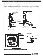
Control panel SEA
Backside view
S1
ХТ1
Р2
Р1
Р3
Р4
31 32
33 34 35 36
ХТ2
ХТ4
ХТ3
1
1
Cable K1
А1
Connecting cable
socket connector
36
35
1
15
14
13
12
11
15
14
13
12
11
1
1
1 2 3 4
5
A3- No.1
to the control
panel SEA
1
2
3
4
5
31 32
33
34
35
36
37
38
39
40
ХТ1
ХТ3
L
N
25
21
22
23
24
15
14
13
12
11
ХТ2
ХТ4
ХТ5
А2
Cable K1
5
1
2
3
4
X1
12 V
N
L
Т1
Transformer unit T1
Ventilation unit
Po
w
er cable with a plug
1
2
3
4
5
31 32
33
34
35
36
37
38
39
40
ХТ1
ХТ3
L
N
25
21
22
23
24
15
14
13
12
11
ХТ2
ХТ4
ХТ5
5
1
2
3
4
to the ne
xt unit
A3- No.2
Jumper JMP1
Cable K1
Cable K2
Jumper JMP1
Connecting cable socket connector
Controller PCB
Controller PCB
Connecting cable
socket connector
Power cable
~120 V or ~230 V
Power cable
~120 V or ~230 V
Connec
ting cable
socket c
onnec
tor
ventilation unit No.2
ventilation unit No.2
31
32
31
32
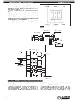
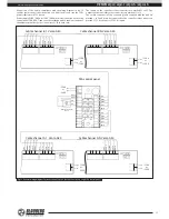
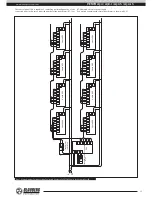
Up to 12 Vento A50 units may be connected to a single SEA control panel
powered by the 40W power transformer AT-40, fig. 20.
First connect the 12W transformer wire leads to the contacts A1:35, 36 of the
controller A1 (SEA) using the socket connector at the cable K2. The cable is
included into delivery set of the 40W transformer model.
Then connect the first unit A3-No.1 to the contacts A1:11-15 of the controller
SEA using the connecting cable supplied with the first unit. Connect the
second unit A3-No.2 (contacts A2: 21-25) to the first unit (contacts A2: 11-15)
using the connecting cable supplied with the second unit.
Connect all the other units, up to 12 items, in the same way.
Connect power supply (230 V / 50 Hz or 120 V / 60 Hz, depending on the unit
model) to the contacts A2: 31,32 of each unit.
The fan impeller rotation direction is determined by position of the jumper
JMP1 on the PCB of A2 unit: the leftmost position sets the unit to extract mode
(Flow Out) and the rightmost position sets the unit to supply mode (Flow In).
The jumper is used to set direction for each fan in the group. The transformer
unit is connected to power mains through the power cable with a plug, which
is prewired to the transformer unit terminal block by the manufacturer.
Fig. 20. Wiring diagram for connection up to 12 VENTO A50 units to SEA controller with AT-40 transformer

