background image

5

EN

Assembly

A

B

B

A

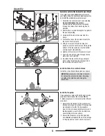
Install the Video Transmitter Antenna

Install the video transmitter antenna as shown.

NOTICE:

 Never power on the video transmit-

ter without the antenna installed. Powering 
on without the antenna will damage the 
transmitter.

Assemble and Install the Optional Camera Mount

If you wish to use an additional camera to record 
your fl ights, follow the directions below to assemble 
and install the optional video camera mount.

1. Assemble the camera mount as shown 

(A).

Do not fully tighten the screws.

Use removable thread locking compound 
to keep the screws from loosening due to 
vibration.

2. Remove the 8 screws holding the top plate to 

the quadcopter 

(B).

3. Carefully lift the top plate away from the 

frame.

4. Position the tabs of the camera mount into 

the slots in the top frame.

5. Using 4 screws and thread locking com-

pound, secure the camera mount through the 
bottom of the top plate and into the bottom 
camera mount standoffs 

(C).

6. Tighten all the screws in the camera mount.
7. Feed a hook and loop strap through the top 

plate slots as shown 

(C)

.

8. Re-attach the top plate to the quadcopter 

frame using thread locking compound and 
the 8 screws removed in step 2.

Install the Propellers

The quadcopter comes with both 2 and 3-blade 
propellers. Install either the 2-blade 

OR

 the 

3-blade propellers. Do not combine the different 
propellers.

1. Refer to the illustration for the proper motor 

rotation and propeller location. The propellers 
are labelled as 

A

 or 

B.

 The 

A

 propellers 

mount to the clockwise rotating motors and 
the 

B

 propellers mount to the counterclock-

wise rotating motors as shown.

2. Secure the propellers using 4 fl anged lock 

nuts. 

Do not

 overtighten the nuts as damage 

to the propellers or motor shafts may result.

A

B

C

Содержание BLH02000

Страница 1: ...Instruction Manual Bedienungsanleitung Manuel d utilisation Manuale di Istruzioni ...

Страница 2: ...o operate the product correctly can result in damage to the product personal property and cause serious injury This is a sophisticated hobby product It must be operated with caution and common sense and requires some basic mechanical ability Failure to operate this Product in a safe and responsible manner could result in injury or damage to the product or other property This product is not intende...

Страница 3: ...Optional Video Camera 9 Preparing the Conspiracy Quadcopter for Flight 10 Flight Mode and Rate Selection 10 Flying the Conspiracy Quadcopter 10 Post Flight Inspection and Maintenance Checklist 10 Troubleshooting Guide 11 Parts Explosion 12 Parts Listings 12 Optional Parts 12 Limited Warranty 13 Warranty and Service Contact Information 14 FCC Information 14 IC Information 14 Compliance Information ...

Страница 4: ... for flying Flying Checklist Always turn the transmitter on first Plug the flight battery into the lead from the ESC Allow the ESC to initialize and arm properly Fly the model Land the model Unplug the flight battery from the ESC Always turn the transmitter off last FPV Camera Power Lead Video Transmitter LED Panel Video Transmitter Antenna Port Video Transmitter Antenna Optional Camera Mount Flight C...

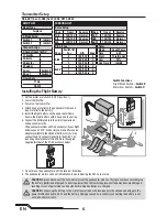
Страница 5: ...lots in the top frame 5 Using 4 screws and thread locking com pound secure the camera mount through the bottom of the top plate and into the bottom camera mount standoffs C 6 Tighten all the screws in the camera mount 7 Feed a hook and loop strap through the top plate slots as shown C 8 Re attach the top plate to the quadcopter frame using thread locking compound and the 8 screws removed in step 2...

Страница 6: ... loop strap 6 Connect the battery cable to the aircraft power lead noting correct polarity The quadcopter utilizes an XT 60 connector If your flight battery uses an EC3 connector you may either use an adapter available in the Optional Parts list or you may connect the EC3 connector directly to the XT 60 The round negative terminal of the EC3 fits in the angled negative terminal of the XT 60 as shown...

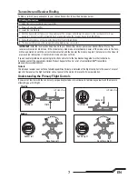
Страница 7: ... of your specific transmitter to enter Bind Mode 6 The receiver LED glows solid orange indicating binding was successful IMPORTANT After the receiver has been bound to your transmitter always power your transmitter on first so the receiver will not enter bind mode If the model enters bind mode unintentionally power off the model ensure the trans mitter is powered on with the correct model selected ...

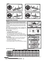
Страница 8: ...tion section 4 Press and hold the button again for 2 seconds to exit and lock the display Band Selection 1 Press and hold the button for 2 seconds to enter Channel Select 2 Press and hold the button again for 2 seconds to swich from Channel Select to Band select 3 Press the button to cycle through the Bands 1 5 4 Press and hold the button for 2 seconds to exit and lock the display Using the Video ...

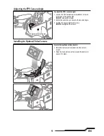
Страница 9: ...amera up or down to the desired angle 3 Tighten the angle adjustment screws DO NOT overtighten the screws To install an optional video camera 1 Place the camera not included into the camera mount 2 Wrap the hook and loop strap around the camera to secure it in place Adjusting the FPV Camera Angle Installing An Optional Video Camera Angle Adjustment Screw ...

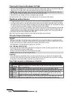
Страница 10: ...ne the performance according to your flying style Refer to the Transmitter Setup for transmitter switch selection and specific setup information Preparing the Conspiracy Quadcopter for Flight 1 Before each flight ALWAYS power on the transmitter before connecting the flight battery to the quadcopter After each flight disconnect the flight battery from the quadcopter before powering off the transmitter NO...

Страница 11: ... before use Difficulty binding Transmitter too near aircraft during binding process Power off the transmitter Move the transmitter a larger distance from the aircraft or shield the aircraft from the transmitter using your body Disconnect and reconnect the flight battery to the quadcopter Follow the binding instructions Bind switch or button was not held while transmitter was powered on Power off tr...

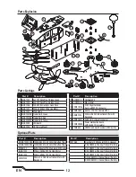
Страница 12: ...mitter Only Optional Parts Part Description 1 BLHA1002 5x4 FPV Race Prop 2Blade Green 2 BLHA1003 5x4 FPV Race Prop 3Blade Green 3 BLHA1006 20A ESC BLHeli Opto Quad Pack 4 BLHA1021 2205 2350Kv FPV Racing Motor 5 BLH02001 Main Frame 6 BLH02002GR Frame Skirt Green 7 BLH02002RE Frame Skirt Red 8 BLH02002YE Frame Skirt Yellow 9 BLH02003 LED Board 10 BLH02004 HD Camera Mount Part Description 11 BLH02005...

Страница 13: ...e you in the event that you may need any assistance For questions or assistance please visit our website at www horizonhobby com submit a Product Support Inquiry or call the toll free telephone number referenced in the Warranty and Service Contact Information section to speak with a Product Support representative Inspection or Services If this Product needs to be inspected or serviced and is compl...

Страница 14: ...eceiving antenna Increase the separation between the equipment and receiver Connect the equipment to an outlet on a circuit different from that to which the receiver is connected This device complies with part 15 of the FCC rules Operation is subject to the following two conditions 1 This device may not cause harmful interference and 2 this device must accept any interference received including in...

Страница 15: ...o ModelMatch EC3 and the Horizon Hobby logo are trademarks or registered trademarks of Horizon Hobby LLC The Spektrum trademark is used with permission of Bachmann Industries Inc All other trademarks service marks or logos are property of their respective owners Created 06 16 51540 BLH02000 ...

Отзывы: