


1301-C00 page 7/56
2.6 Piping
Never draw piping to the pump flanges
by force.
This may cause dangerous strains
within the pump case and misalignment
between the pump and driver.
The result could be serious injury and
damage to the equipment.
Hazardous pressure
can cause personal
injury or property
damage
Proper piping details are provided by the Hydraulics Institute
Standards.
Piping Strain
The suction and discharge pipe flanges must be aligned
concentric and parallel to the pump flanges. The piping must
be supported independently near the pump, and all flanges
must match so that no strain will be transmitted to the pump
after the nuts and bolts have been securely fastened. When
tightening the nuts and bolts, always tighten bolts 180°
opposite from each other in an alternating pattern to achieve
even gasket compression.
The piping system should be designed with sufficient inherent
flexibility to withstand thermal expansion without creating
excessive forces at the flanges. The piping must also be
arranged and supported so that no excessive stress can be
transmitted to the pump, either due to the weight of the pipe
and fluid, or to its expansion and contraction.
NOTICE:
Do not draw the piping into the pump by force as this will
cause strain on the pump resulting in reduced seal and
bearing life.
Excessive strain on a pump may be the result of:
1. Thermal expansion and contraction of the piping. This
indicates improper piping design. Expansion joints or
loops may have to be installed.
2. Improper pipe support. Frequent problems arise from
indiscriminate use of rod hangers (instead of spring
hangers), anchors or restraints used during the pipe
installation.
3. Misalignment of the pipe flanges to the pump suction and
discharge flanges.
Suction Piping
Rules of Thumb:
Generally the suction piping is no more than one size larger
than the pump nozzle. Suction lines should never be smaller
than the pump suction nozzle.
To prevent cavitation in the pump, suction line velocities
should not exceed 10ft./sec (3 m/sec).
Typical fluid velocity guidelines are 4 to 6 ft./sec (1 to 2
m/sec) for suction and 6 to 10 ft./sec (2 to 3 m/sec) for
discharge.
The pressure drop across permanent suction strainers must
be considered when determining suction pressure at pump
inlet.
Install valve stems and tee branches perpendicular to, not
parallel to, the pipe centerline.
NPSH:
The pump must have enough positive suction head to prevent
cavitation. The NPSH available (NPSHa) must always be
greater than the NPSH required (NPSHr). Refer to the pump
performance curve for NPSHr information.
For submerged suction, the inlet must be located deep enough
to prevent vortexing. If necessary, provide vortex breakers in
the suction vessel to prevent vortex formation.
The suction piping must be free of air pockets. Use an
eccentric reducer if joining suction piping of different sizes to
reduce the chance of an air pocket forming at the junction.
Reference recommended configuration below.
NOTICE:
Never control the pump flow by throttling a valve in the
suction line. The function of the suction valve is to isolate
the pump from the system during maintenance.
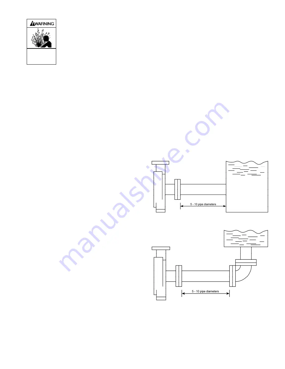
It is recommended to have a straight length of suction piping,
equal to at least 5 to 10 times the diameter of the pipe, directly
in front of the pump suction flange. Never place an elbow
directly in front of the suction flange.
Elbows in suction piping should be of the long radius type.
Separate suction lines are recommended when more than one
pump is operating from the same source of supply.
Suction strainers must have a total free area of at least 3x the
suction pipe area.
Preferred piping configuration – at least 5-10 diameters of
straight pipe between the source and the pump suction.
Elevated source preferred piping - to be in one plane, again
with at least 5-10 diameters of straight pipe between the elbow
and the pump suction.
Содержание SYSTEM ONE
Страница 26: ...1301 C00 page 25 56 8 0 PUMP ASSEMBLY DRAWINGS AND PARTS LIST 8 1 Pump Assembly Parts List Frame SD Horizontal ...
Страница 27: ...1301 C00 page 26 56 8 2 Pump Assembly Parts List Frame S Horizontal 6 1 ...
Страница 28: ...1301 C00 page 27 56 8 3 Pump Assembly Parts List Frame S Horizontal 8 ...
Страница 29: ...1301 C00 page 28 56 8 4 Pump Assembly Parts List Frame A and IPP Frame A ...
Страница 30: ...1301 C00 page 29 56 8 5 Pump Assembly Parts List LD17 and IPP LD17 ...
Страница 31: ...1301 C00 page 30 56 8 6 Pump Assembly Parts List Vortex Frame A and IPP Vortex Frame A ...
Страница 32: ...1301 C00 page 31 56 8 7 Pump Assembly Parts List Vortex LD17 and IPP Vortex LD17 ...
Страница 33: ...1301 C00 page 32 56 8 8 Pump Assembly Parts List Frame M ...
Страница 55: ...1301 C00 Page 54 56 notes ...
Страница 56: ...1301 C00 Page 55 56 notes ...


