


10
CHAPTER 3.
INSTALLATION
3.2 Connectors and Jumpers
3.2.1 Front Side Connectors
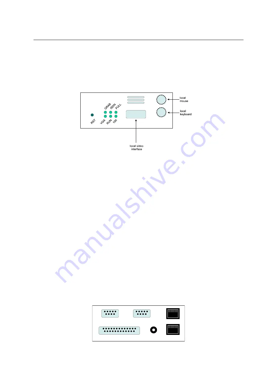
Figure
shows the connectors on RAS-PutIn’s front side.
Figure 3.3: RAS-PutIn Front Side Connectors
RST
Pushing this button performs a reset of RAS-PutIn. One has to use this button for the
initial configuration of RAS-PutIn
VGA
Indicates, that the VGA input is active and a video signal is received by RAS-PutIn
RUN
Indicates whether the RAS-PutIn system is running or not
100
Indicates that the Ethernet connection is in 100 Mbit mode
FULL Indicates that the Ethernet connection is in full-duplex mode
ISDN
Indicates that the ISDN subsystem is available and active (EMEA version only)
GRAB Indicates that a remote user is logged onto RAS-PutIn and the video engine is outputting
data
In case you want to connect a local console to the host system besides RAS-PutIn, you can
attach monitor, keyboard and mouse to the according RAS-PutIn connectors on its front.
3.2.2 Rear Side Connectors
Figure
shows the connectors on RAS-PutIn’s rear side.
ISDN
Ethernet
Serial 1
Keyboard/Video/Mouse
Power
Serial 2
Figure 3.4: Rear Side Connectors
SUB-D 9 Serial 1 The standard serial connector is used in multiple ways:
Содержание RAS-PutIn
Страница 1: ...RAS PutIn Installation and User Guide Based on Firmware 03 02 07 ...
Страница 4: ...iv ...
Страница 8: ...viii Contents ...
Страница 12: ...xii List of Tables ...
Страница 30: ...18 CHAPTER 4 CONFIGURATION ...
Страница 76: ...64 CHAPTER 5 USAGE ...
Страница 80: ...68 APPENDIX A GLOSSARY ...
Страница 82: ...70 APPENDIX B RAS PUTIN VIDEO MODES ...
Страница 88: ...76 APPENDIX D PIN ASSIGNMENTS ...
Страница 92: ...80 APPENDIX F SPECIFICATIONS ...


