Cable installation
26
Model LRA2900A RAS Getting Started Guide
2 • Hardware installation
Connecting the 10/100Base-T Ethernet port to an Ethernet switch or hub
The 10/100Base-T Ethernet port (see figure 7 on page 25) is designed to connect to an Ethernet switch or
hub. Connect a straight-through CAT-5 cable (one wired as shown in figure 8) between the RAS and the hub/
switch.
Figure 8. Straight-through RJ-45-to-RJ-45 Ethernet cable diagram
Connecting the 10/100Base-T Ethernet port to an Ethernet-capable workstation
The 10/100Base-T Ethernet port can connect to a single Ethernet-capable workstation by means of a cross-
over cable. Refer to figure 9 to assemble a cross-connect cable that will connect between the NIC Ethernet port
in the workstation and the RAS 10/100Base-T Ethernet port.
Figure 9. Cross-over RJ-45-to-RJ-45 Ethernet cable diagram
Connecting the EIA-561 RS-232 configuration port
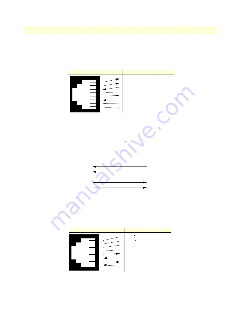
Install the supplied DB-9-to-RJ-45 cable between the RAS RS-232 port (see figure 7 on page 25) and an open
serial port on your computer. If you need to assemble your own cable, refer to the pinout diagram in figure 10.
Figure 10.
DB-9-to-RJ-45 cable
diagram
RJ-45 Jack
(TX+) Transmit Data +
(TX-) Transmit Data -
(RX+) Receive Data +
4
5
(RX-) Receive Data -
7
8
1
2
3
4
5
6
7
8
Direction
Signal Name
3
1
2
6
Output
Output
Input
Input
10Base-T Workstation
RJ-45 Pin No.
RAS 10/100Base-T Port
RJ-45 Pin No.
(TX+)
(TX-)
(RX+)
(RX-)
1
2
3
6
(RX+)
(RX-)
(RX+)
(TX-)
3
6
1
2
6 DSR
1 CD
4 DTR
5 SG
2 RD (driven by access server)
3 TD (received by access server)
8 CTS (driven by access server)
7 RTS (received by access server)
1
2
3
4
5
6
7
8
Wired together
(No other electrical
connection)
RJ-45 Jack
Signal Name
DB-9


