10
KT-140-7 RUS
3
Wassergekühlte Zylinderköpfe
• Optionbei
-4J-13.2(Y)..6F-50.2(Y)
-2T.2(Y)..6F.2(Y)
-III(Y)..V(Y)
• Standardbei
-VIW(Y),VIIW(Y)
- NH
3
-Ausführung der offenen
Verdichter: W2TA .. W6FA
Für korrosives Kühlwasser (z. B. See-
wasser) ist eine Kunststoff beschichte-
te Ausführung erhältlich.
3.1 Montage
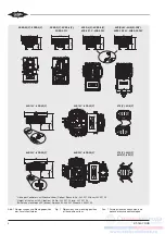
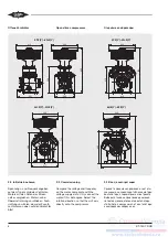
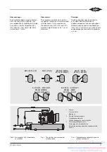
Kühlwasser entsprechend Abbildung 2
anschließen.
Bei 4- und 6-Zylinder-Verdichtern ist
sowohl Reihen- als auch Parallel-
schaltung möglich. Bei Parallelschal-
tung darf die Mindest-Wassermenge
von 150 I/h für jeden Zylinderkopf
nicht unterschritten werden.
Kühlwasser-Temperatur
• Eintritt:
Das Kühlwasser für die Zylinder-
köpfe sollte aus dem bereits
erwärmten Kühlwasser des Ver-
flüssigers abgezweigt werden.
• Austritt:
Die Kühlwasser-Temperatur soll-
te 50°C nicht übersteigen. In der
Regel ist die Wärmeabfuhr ausrei-
chend, wenn die Temperaturdiffe-
renz zwischen Kühlwasser-Eintritt
und -Austritt 5 .. 10 K oder der
Wasser-Durchsatz ca. 150 I/h
beträgt.
Stillstand des Verdichters
Beim Abschalten des Verdichters
muss der Kühlwasser-Zufluss zum
Zylin derkopf unterbrochen werden
(z. B. Wasserregler, Magnetventil),
um eine Rückkondensation von Kälte-
mittel in den Zylinderkopf zu ver-
meiden.
Flexible Leitungselemente
Bei elastischer Aufstellung des Ver-
dichters sollten flexible Leitungsele-
mente eingebaut werden (Abb. 2).
3
Water cooled cylinder heads
• Optionfor
-4J-13.2(Y)..6F-50.2(Y)
-2T.2(Y)..6F.2(Y)
-III(Y)..V(Y)
• Standardfor
-VIW(Y),VIIW(Y)
- NH
3
design of the open drive
compressors: W2TA .. W6FA
For corrosive cooling water (e. g. sea
water) a plastic-coated version is
available.
3.1 Assembly
Connect the cooling water according
to figure 2.
Four and six cylinder compressors
may be connected in series or in par-
allel. For parallel connection a mini-
mum water flow rate of 150 I/h at each
cylinder head must be ensured.
Cooling water temperature
• Inlet:
The cooling water for the cylinder
heads should preferably be
supplied from the already warmed
cooling water of the condenser.
• Outlet:
The cooling water temperature
must not exceed 50°C. Adequate
heat transfer is normally achieved
when the inlet / outlet water tem-
perature difference is between 5
and 10 K or with a water volume
fIow of approx. 150 l/h.
Compressor standstill
When the compressor is off, the
cooling water supply to the cylinder
heads must be interrupted (e. g. water
regulator, solenoid valve) to avoid
condensation of refrigerant back into
the cylinder head.
Flexible pipe elements
If the compressor is flexibly mounted,
the use of flexible pipe elements are
recommended (figure 2).
3
Водоохлаждаемые головки
цилиндров
• Опция для:
- 4J-13.2(Y) .. 6F-50.2(Y)
- 2T.2(Y) .. 6F.2(Y)
- III(Y) .. V(Y)
• Стандарт для:
- VI W(Y), VII W(Y)
- NH
3
модификация открытых
компрессоров: W2TA .. W6FA
Для защиты от коррозийного воздействия
охлаждающей воды (например, морской
воды) доступно полимерное покрытие
охлаждающего тракта.
3.1 Сборка
Присоедините подвод охлаждающей
воды в соответствии с рис. 2.
Для 4-х и 6-ти цилиндровых компрес-
соров возможно последовательное
и параллельное подключение линий
охлаждения. При параллельном
подключении необходимо обеспечить
минимальный объемный расход воды
150 л/час на каждую головку цилиндров.
Температура охлаждающей воды
• На входе:
Охлаждающая вода для головок
цилиндров не должна смешиваться с
уже нагретой водой в конденсаторе.
• На выходе:
Температура охлаждающей воды не
должна превышать 50°C. Достаточный
отвод тепла, как правило, дости-
гается, если разница температур
между охлаждающей водой на входе
и на выходе составляет 5 .. 10 К или
при объемном расходе воды прим.
150 л/час.
Отключение компрессора
При выключении компрессора должна
быть прекращена подача охлаждающей
воды к головкам цилиндров (например,
при помощи регулятора расхода воды,
электромагнитного клапана), чтобы не
допустить конденсации хладагента в
головках цилиндров.
Гибкие соединительные патрубки
Для не жесткой установки компрессора
должны использоваться гибкие
соединительные патрубки (см. рис. 2).

