background image

11


4. FOR DORRIS MIXER TRANSMISSION

          (OBSOLETE -N/A) BEFORE SERIAL NO. 55665

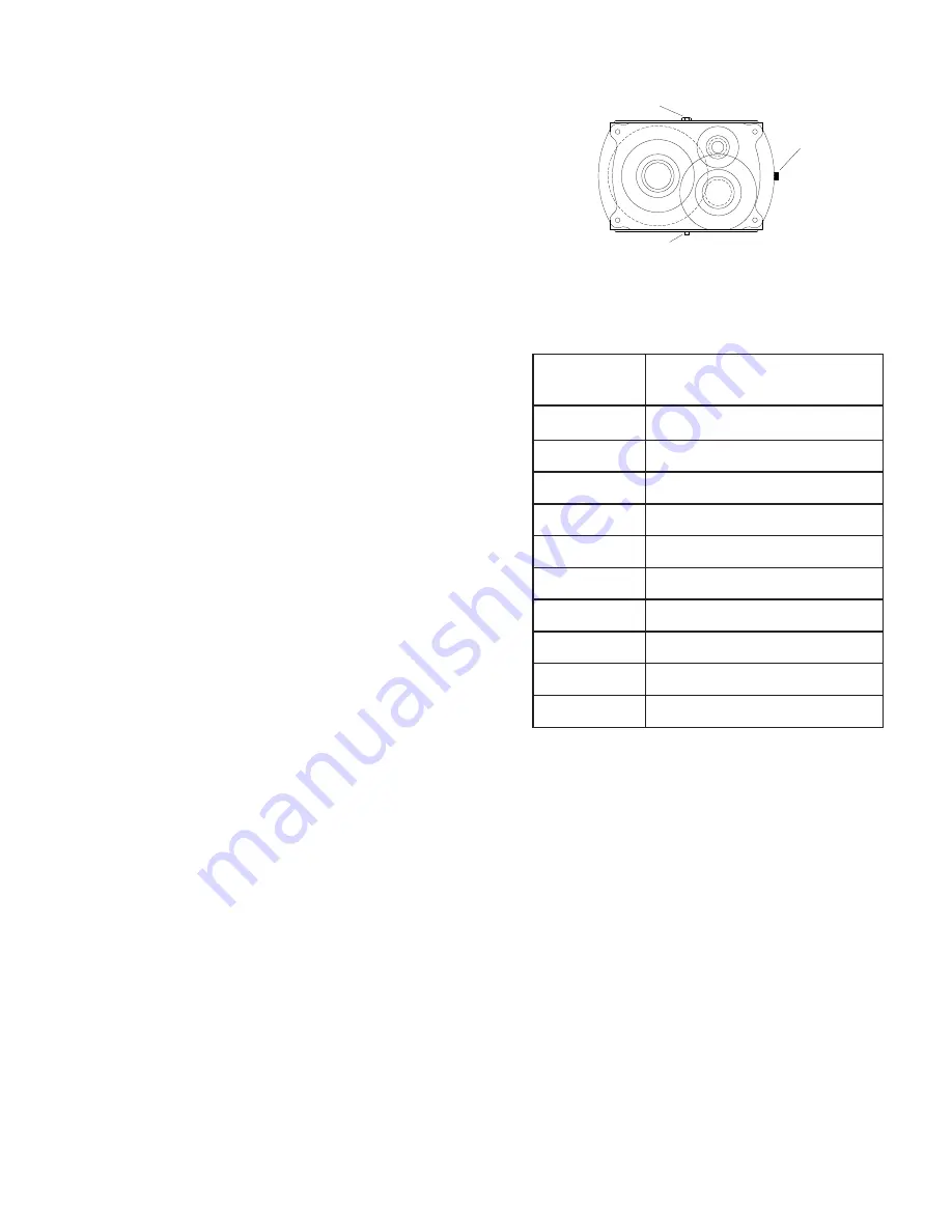
DORRIS MIXER TRANSMISSION: Oil in the mixer 

transmission should be changed after the first four (4) weeks

of operation. This is to remove the “run in” oil and also any

small metal shavings that may have been generated during 

the initial mating of the gears. After the first oil change,

subsequent changes should be performed every six (6)

months. After draining the oil, refill the unit to the “level”

plug (1 qt.) at the center of the transmission with a 

petroleum based rust and oxidation (R&O) inhibited gear

oil. Viscosity Range for 15-75° F (-9 - 24° C) is 

AGMA Lube No. 3 or ISO Grade 100.  

TO CHANGE OIL:


a. Unplug mixer/grinder from power source and perform 

           lockout/tagout procedures. 


b. Remove rear drive cover. 


c. Remove breather plug from top of transmission and oil

           level plug from side of transmission.  


d. With a container in place to catch old oil, remove the 

           magnetic drain plug from the bottom of the transmission. 


e. When all oil has drained, clean the drain plug and

           replace into the transmission. 


f. Refill transmission with approx. one (1) quart of the

          recommended gear oils or equivalent. Or until oil

          appears at bottom of oil level sight hole.  


g. Replace breather and oil level plugs.


h. Carefully turn mixer transmission pulley by hand to 

           lubricate internal gears. 


i. Reinstall rear drive cover. 

D. MIXER DRIVE BELT TENSION

      1. Unplug mixer/grinder from power source and perform lockout/tagout procedures.

      2. Remove rear drive cover.  

      3. Loosen the four bolts holding the 1HP motor to its mounting plate.  

      4. Slide 1HP motor away from mixer transmission. 

      5. When approximately 

½” total belt flex has been attained, re-tighten motor bolts. 

      6. Reinstall rear drive cover.  

E. MAIN DRIVE CHAIN AND SPROCKET LUBRICATION:

The main drive chain has been pre-lubricated at the factory to protect it against dirt and moisture. Chain life

will vary appreciably depending upon its lubrication. The better the lubrication, the longer the chain life. 
Lubrication effectiveness will vary with the amount of lubricant and frequency of application. Ideally, a lubricant

film should always be present between the working parts. Manually lubricate the chain as often 

as is needed 

(possibly once a week). 

NEVER

 exceed three months without lubricating. 

Lubricating just outside of the chain does little good. Apply lubrication on the inside of the chain span so that

it will work through the moving parts and joints by centrifugal force as the chain rotates and reach the area

where one surface “scrubs” another.  

SUGGESTED POPULAR NAME BRANDS:

R & O GEAR OILS

(RUST & OXIDATION INHIBITED)

COMPANY

ISO VISCOSITY GRADE

100 (AGMA3)

AMOCO

American Ind’l Oil 100

CHEVRON

Machine Oil R & O ISO 100

CITGO

Pacemaker Oil 100

CONOCO

Dectol R & O Oil 100

EXXON

Teresstic 100

MOBIL

DTE Heavy

PHILLIPS

Magnus Oil ISO VG 100

SHELL

Morlina Oil 100

SUN

Sunvis 9100

TEXACO

Regal Oil R & O 100

BREATHER PLUG

MAGENTIC DRAIN PLUG

OIL

LEVEL

PLUG

Содержание AFMG-52

Страница 1: ...PERATING AND SERVICE MANUAL STARTING WITH SERIAL NO 52001 STARTING WITH SERIAL NO 52101 SIDE OPENING LID STARTING WITH SERIAL NO 52345 35 INLET TRI DIRECTIONAL LID IMPORTANT NOTICE This Manual contains important safety instructions which must be strictly followed when using this equipment ...

Страница 2: ... ASSEMBLIES 19 CONNECTION INSTRUCTIONS FOR TANDEM OPERATION 25 26 OPERATOR S SIGNATURE PAGE 29 GRINDING BOWL INSTALLATION 8 NORD TRANSMISSION 9 10 DORRIS TRANSMISSION 11 MIXER DRIVE BELT TENSION 11 MAIN DRIVE CHAIN AND SPROCKET LUBRICATION 11 MIXER DRIVE CHAIN TENSION 12 CHAIN REPLACEMENT 12 OPTIONAL EAGLE BELT DRIVE SYSTEM 14 15 PRODUCT MIXER SAFETY COVERS LID LOCKS 20 JOURNAL BOX 21 ELECTRIC FOO...

Страница 3: ...ined in this manual are not binding The manufacturer reserves the right to introduce any modification without updating the manual 1 No one should use or service this machine without proper training and supervision All operators should be thoroughly familiar with the procedures contained in this Manual Even so BIRO cannot anticipate every circumstance or environment in which its products will be us...

Страница 4: ...WAYS Lock Machine Castors After Moving This Machine NEVER Use This Machine For Non Food Products NEVER Operate Machine With Product Mixer Safety Cover Open or Removed or Magnetic Interlock Switch By Passed ALWAYS Turn Off Unplug Machine From Power Source and Perform Lockout Tagout Procedure to this Machine BEFORE Attempting to Unjam or Unclog Cleaning or Servicing NEVER Leave Machine Unattended Wh...

Страница 5: ... Then take machine off shipping pallet 3 This machine is shipped with the adjustable legs fully retracted The legs allow for a height adjustment from the floor to centerline of bowl 239 16 minimum to 331 16 maximum 4 This machine weighs approximately 750 pounds To avoid accidents block up machine after raising to desired operating height 5 The adjustable legs can now be unbolted and lowered to the...

Страница 6: ...kw 220 60 E 48 5 0 50669 1 5 HP 1 1kw 440 60 E 38 2 5 52740 1 5 HP 1 1kw 460 60 E 36 2 4 52739 1 5 HP 1 1kw 575 60 E 33 1 9 52729 1 5 HP 1 1kw 220 50 E 48 6 0 50669 1 5 HP 1 1kw 380 50 E 39 3 5 52732 1 5 HP 1 1kw 415 50 E 39 3 2 52732 1 5 HP 1 1kw BALDOR MOTOR Voltage Cycles Overload Amps Item No 200 60 E 70 25 53925 7 5 HP 5 6kw 208 60 E 69 24 54219 7 5 HP 5 6kw 220 60 E 67 23 52609 7 5 HP 5 6kw ...

Страница 7: ...G 16 Check placement of all warning labels and Manual Machine is now ready for trained operators to process product 17 Use meat deflector attached to grinding bowl to eliminate meat splatter 18 Contact your local Distributor or BIRO directly if you have any questions or problems with the installation or operation of this machine 10 Two sets of green and red pushbuttons are located on the front of ...

Страница 8: ...grinder have a container for receiving ground product at the output end of the grinding bowl 2 FIRST GRIND 3 SECOND GRIND 4 Unplug machine from power source and perform lockout tagout procedures a Fill Product Hopper Maximum 200 Pounds close Product Mixer Safety Cover b Push the mix green start button only During this mix operation seasonings may be added through the sight holes in the Product Mix...

Страница 9: ...ng a high percentage of free alkali or acid 3 Do not use a detergent containing a high percentage of tri sodium phosphate or meta silicate Tin is reactive to both 4 Rinse well and dry thoroughly after washing to remove agents that may be reactive to tin 5 If sterilizing agent containing chlorine is used the tinned surface must be thoroughly rinsed Chlorine is corrosive to tin 6 Dry thoroughly afte...

Страница 10: ...VER Bypass Alter or Modify This Equipment in Any Way From Its Original Condition PROMPTLY REPLACE Any Worn or Illegible Warning Labels USE ONLY GENUINE BIRO Parts and Accessories Properly Installed ROTATING GRINDING AUGER ROTATING MIXING PADDLE TO AVOID SERIOUS PERSONAL INJURY 3 When fully seated turn the lock arm counterclockwise so the protruding arm is behind the lock set screw bracket Tighten ...

Страница 11: ... Polyalphaoelfin Polyalphaoelfin Mineral Mineral Polyglycol No No Yes Aral Degol GS 680 BP Enersyn SG XP 680 Texaco Pinnacle 680 Shell Omala HD 680 Klober Klubersynth GH 6 680 Mobil SHC 636 Tribol 800 680 The listing below offers suggestions on the manufacturers of recommended lubricants Use synthetic oil Polyglycol Base between 14 175 with an ISO Viscosity Class of ISO VG 680 NORD GEAR CORP 800 N...

Страница 12: ...ive shaft 12 Assemble the lock arm assembly Item No 53852 onto the front of the hopper on the paddle assembly 13 Be sure the transmission mounting plate is tight to the mounting brackets 14 Does the lock arm assembly turn free with the paddle assembly If there were shims on the old mixer transmission assembly to the mounting brackets you will need to use them again to align the lock arm assembly w...

Страница 13: ...RIVE BELT TENSION 1 Unplug mixer grinder from power source and perform lockout tagout procedures 2 Remove rear drive cover 3 Loosen the four bolts holding the 1HP motor to its mounting plate 4 Slide 1HP motor away from mixer transmission 5 When approximately total belt flex has been attained re tighten motor bolts 6 Reinstall rear drive cover E MAIN DRIVE CHAIN AND SPROCKET LUBRICATION The main dr...

Страница 14: ... adjusting studs counterclockwise Grasp motor and pull toward adjusting stud Be sure to turn both adjusting studs the same amount and evenly Total chain flex should be to Be sure to keep motor shaft parallel with auger drive shaft To Tighten Chain Tension Turn motor adjusting studs clockwise Be sure to turn both adjusting studs the same amount and evenly Total chain flex should be to Do not over t...

Страница 15: ...S10Z Apply food approved Silicone Sealant over the Set Screw 9 The Tub and Seal must be clean and dry Use Rubbing Alcohol Apply Biro Item No 53953A 1 adhesive only use half the tube 05 ounce around the inside of the Mixer Shaft Seal and inside of the Tub wall Wipe away excess adhesive Adhesive working life 20 seconds 10 Slide Ring Item No ST88 onto the Mixer Drive Shaft concave side toward the Sea...

Страница 16: ...14 OPTIONAL EAGLE BELT DRIVE SYSTEM ...

Страница 17: ... as follows a Loosen the four 4 motor mounting bolts slightly A b Advance the jacking screws turn each be sure to advance both screws an equal amount B Do not rely on feel for the proper belt tension as this typically results in belts that are under tensioned Loose belts will fail due to ratcheting jumping a tooth tooth shearing and breakage I REPLACING ELECTRICAL SUPPLY CORD Always turn off unplu...

Страница 18: ...9 30 28 27 11 10 L3 L2 L1 GRD 54 56 55 31 37 37A 9 36 35 34 33 33A 53 13 12 8 PADDLE DETAIL SEE ABOVE 25C 25D 23 24 26 25 22 20 21 15 18 19 16 46 47 42 44 50 48 49 51 17 14 8A 1 1A 1B 5 39 38 8B 3 6 6 4 7 2 41 40 5 45 43 26A 26B 58 27 27C 27B 27A 27A 27B 27C 57 17 ...

Страница 19: ...COSK Rear drive cover COS kit 55092 COS Rear drive cover w handles magnet 14688 4 point knob AL 14688 COS Locking knob AL 8 req 57219 Screw COS rear drive cover 8 req FW06S Flat washer SS FW16S Flat washer 5 16 SS HHS025S Hex head screw 20 x SS HHS049S Hex head screw 5 16 18 x SS HHS050S Hex head screw 5 16 18 x SS Description Item No Fig HHS055S Hex head screw 5 16 18 x SS HN07S Hex nut 10 24 SS ...

Страница 20: ...27 Main sprocket 141 tooth 20 52101 on 56222 Safety cover torsion spring L H 52101 on 55095 Right side skirt 90 inlet 52001 to 52344 15B HHS128S Hex head screw 13 x 1 SS 30 LW30S Lock washer SS 31 35220 Motor cord SO 14 4 x 42 32 C776 Terminal ring 10 NOT SHOWN 241 LN Lock nut 34 35 57050 Safety cover hinge rod side opening 57153 Tri directional hinge rod for front opening 52345 on 27 56045 Hinge ...

Страница 21: ...adapter SS 54278C Auger shear pin 57022S Auger assembly complete SS 57023S Bowl with plate pins SS FHS36S Shear pin fasteners 20 x 1 SS HK52 56 Knife drive pin coarse thread HP52 Bowl plate pin 3 req HR52S Bowl ring SS Description Item No MC52 17 Knife 4 blade MC52 18 125 Plate Holes 3 5 mm MC52 18 156 Plate 5 32 Holes 4 0 mm MC52 18 187 Plate 3 16 Holes 5 0 mm MC52 18 375 Plate Holes 9 0 mm OPTIO...

Страница 22: ... Latch mounting bracket R H HNNL15S Hex nut 20 nylok 3 ea RHS24S RHS31S Round head screw 20 x 1 SS 1 ea Roung head screw 20 x SS 2 ea PRODUCT MIXER SAFETY COVER LID LOCK FEATURE S N 54248 ON RETROFITS ON S N 52100 TO S N 54247 Description Item No Fig 55081 Lid lock retrofit kit S N 52100 to 54247 55059 Lid lock 55061 Lever arm assembly 2503 Nylon washer 125 thick 2 ea 2504 Nylon washer 060 thick 4...

Страница 23: ... spring 53693 U Auxillary treadle return spring 53693 W Treadle 53693 H Internal assembly complete 53693 I Actuator 52654 Male plug w 6 cord 5 pole 53693 X One actuator actuator spring assembly 53979 1 Cord 8 w out footswitch 54213 Footswitch w 6 cord plug FOOTSWITCH PARTS LIST 52655 52654 52661 53693 E 53693 D 53693 O 53693 H 53693 M 53693 X 53693 A 53693 F 53693 C 224 2 53693 I 53693 X 53693 U 5...

Страница 24: ... to 24 48 52 inlet 53667 Discharge horn less seal 56 to 24 48 52 inlet 53671 Seal only 24 42 46 48 to 24 48 52 inlet 53673 Discharge horn assembly 48 52 w seal 53933 Seal only 52 56 to 24 48 52 inlet 56135 1 Chub packing discharge horn 52 to 3 dia 53489 Discharge horn less seal TANDEM OPERATION PART LIST includes 53489 53671 BIRO MANUAL TO BIRO AFMG 52 BIRO AFMG 52 TO BIRO AFMG 48 BIRO AFMG 52 TO ...

Страница 25: ...D TUBE AFMG 52 AFMG 52 15 APPROX 23 9 16 31 1 8 62 1 2 APPROX 6 FOOT OVERALL 54 15 16 OPTIONAL LEFT SIDE INLET FEED TUBE AFMG 52 19 APPROX 23 9 16 31 1 8 45 1 2 30 1 4 46 BIRO 3 5 7 HP GRINDERS 1 2 14 7 8 OVERALL LEG LENGTH APPROX 7 FT OVERALL MODEL 1056 1556 OVERALL LEG LENGTH 10 5 8 ...

Страница 26: ...IGNED TO WORK ON BIRO EQUIPMENT ONLY 52 SIZE DISCHARGE HORN ASSEMBLY Item No 57143 Includes Clamp Assembly Item No 57143 11 48 SIZE DISCHARGE HORN ASSEMBLY Item No 57144 Includes Clamp Assembly Item No 57144 11 BIRO MANUAL TO BIRO AFMG 52 BIRO AFMG 52 TO BIRO AFMG 48 BIRO AFMG 52 TO BIRO AFMG 52 ...

Страница 27: ...to the Discharge Horn Step 4 Insert the Discharge Horn with Ring and Clamp Assembly into the Seal pushing it fully against the inlet tube internal fins Attach the lock latches to the tabs on the side of the inlet tube and lock down Tighten the lock knob on the Clamp Assembly Step 5 Move the Discharge Horn of the Second Grind Machine up to the Bowl of the First Grind Machine With the Auger Knife an...

Страница 28: ...26 TANDEM OPERATION ILLUSTRATION FOR 35 INLET ...

Страница 29: ...27 WIRING DIAGRAM ...

Страница 30: ...MOVE ANY SAFETY INTERLOCK SWITCHES OR OTHER SAFETY DEVICES ALWAYS DISCONNEC T POWER SUPPLY BEFORE REMOVING SHROUDS GUARDS COVERS DOORS FENCES PANELS FOR CLEANING SERVICING REASSEMBL ING OR ANY REASON FAILURE TO COMPLY WITH WARNING COULD RESULT IN SERIOUS BODILY INJURY 653PS DO NOT TAMPER BYPASS REMOVE ANY SAFETY INTERLOCK SWITCHES OR OTHER SAFETY DEVICES ALWAYS DISCONNEC T POWER SUPPLY BEFORE REMO...

Страница 31: ...AVE COMPLETELY READ AND UNDERSTAND THIS MANUAL I REALIZE THAT THIS MACHINE IF OPERATED CARELESSLY CAN CAUSE SERIOUS INJURY TO MYSELF AND OTHERS NAME PRINT SIGNATURE SUPERVISOR S INITIALS DATE WARNING READ AND UNDERSTAND THIS ENTIRE MANUAL BEFORE SIGNING BELOW ...

Страница 32: ...quirements which must be performed only by a certi fied electrician BIRO is not responsible for service charges or labor required to replace any part covered by this limited warranty or for any damages resulting from misuse abuse lack of proper or recommended service EXCLUSION OF WARRANTIES AND LIMITATION OF REMEDIES BIRO gives no warranties other than those expressly stated in this limited warran...

Отзывы: