C7SM-1.01
34/70
Service Manual of Cardio 2000
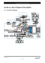
Section 4. Block Diagram/Description
4-1. Circuit Block Diagram
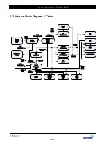
Basic Module
CPU Module
Analog Module
Character LCD
User Interface Module
CPU
DDR3
2G x 2
EMMC
4G
USB OTG
Connector
PMIC
JTAG
Connector
PRINTER ASS’Y
MCU
3.3V, 5V
Power
Isolator
Shield
Driver
ECG AFE
PACE
Detec
-tor
Membrane Keys
Isolator
Thermal
Printer
Header
Step
Motor
Paper
Sensor
Analog Module Connector
Analog Module Connector
User Interface Module Connector
Printer Connector
USB 1 Port
LAN PORT(RJ45)
Touch
controller
Backlight
Power
RS232
Transceiver
Ethernet
Transceiver
Paper
Sensor
Driver
5V, 3.3V,
4.2V
Power
Motor
Driver
TPH Signal
Transceiver
Charger
Power MCU
System Power
Switch
Coin Battery
Buzzer
User Interface Module Connector
PSU Connector
Battery Connector
Ready LED
AC / Battery
Indicator LED
24V
Printer Power
Printer
MCU
Battery Cable
PSU Cable
User Interface Signal Cable
Analog Board Cable
Printer Cable
Character LCD Pin Header
Character LCD Pin Header
Patient Connector
Power
Supply
Unit
Battery
Uart
port
Содержание CardioCare EKG2000
Страница 1: ...EKG2000 SERVICE MANUAL Version 1 0 www ebionet com ...
Страница 47: ...C7SM 1 01 47 70 Service Manual of Cardio 2000 2 Cable LCD Assembly 40Pin FFC Cable Battery Cable Assembly ...
Страница 48: ...C7SM 1 01 48 70 Service Manual of Cardio 2000 QN TPH Cable Motor Assembly Power Switch Cable Assembly ...
Страница 51: ...C7SM 1 01 51 70 Service Manual of Cardio 2000 Bottom Cover Assembly Top Cover Assembly ...
Страница 61: ...C7SM 1 01 61 70 Service Manual of Cardio 2000 Bottom Cover Ass y Printer Module Ass y ...
Страница 62: ...C7SM 1 01 62 70 Service Manual of Cardio 2000 EKG2000 Ass y Battery Ass y ...
Страница 65: ...C7SM 1 01 65 70 Service Manual of Cardio 2000 8 2 CDUI Board Top Bottom ...
Страница 66: ...C7SM 1 01 66 70 Service Manual of Cardio 2000 8 3 CPU Board Top Bottom ...

