User’s Guide
The F3 frame can be connected to three side of the Dynamixel at a 90 degree
angle. There are a total of four ways to connect the frame and the Dynamixel.
There are other additional ways to construct the frame. Refer to the construction
diagram of the robot for more specific information.
3-2. Wiring and Power
Wiring
Wiring is an important part of building the robot. Majority of the problems that
occur with the robot are due to faulty wiring. Severed cable due to insufficient
length, cables getting stuck in between the robot’s joints are some of the
problems that may occur (latter problem mostly occurs due to users wanting to
assemble robot in uncluttered fashion, wiring the cable in narrow joint’s space.)
Also, self-made cables are often the cause of problems. Sufficient cables are
provided so try not to use your own self-made cable. Connect the Dynamixels to
the CM-5 unit. As in the figure below, there are four places on the CM-5 unit
where the cables can be connected.
Four wiring locations for CM-5 are illustrated as follows.
○
3
As in the figure above, the number 1 and 2 bus connectors are located on the
side of the CM-5 unit and the number 4 bus connector is located on the bottom.
The cables should be connected in a daisy chain configuration, as shown in the
figure below.
○
1
○
2
○
4
Front
Back
33
Содержание Robotis
Страница 1: ...Ver 1 00 BIOLOID User s Guide Closer to Real...
Страница 55: ...User s Guide Portion that will be ignored Enable Disable Code Portions that will be ignored 55...
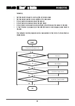
Страница 73: ...User s Guide Move routine Stop Backward Left turn Right turn Melody sound routine 73...
Страница 100: ...User s Guide Transmitter behavior control program Receiver behavior control program 100...


