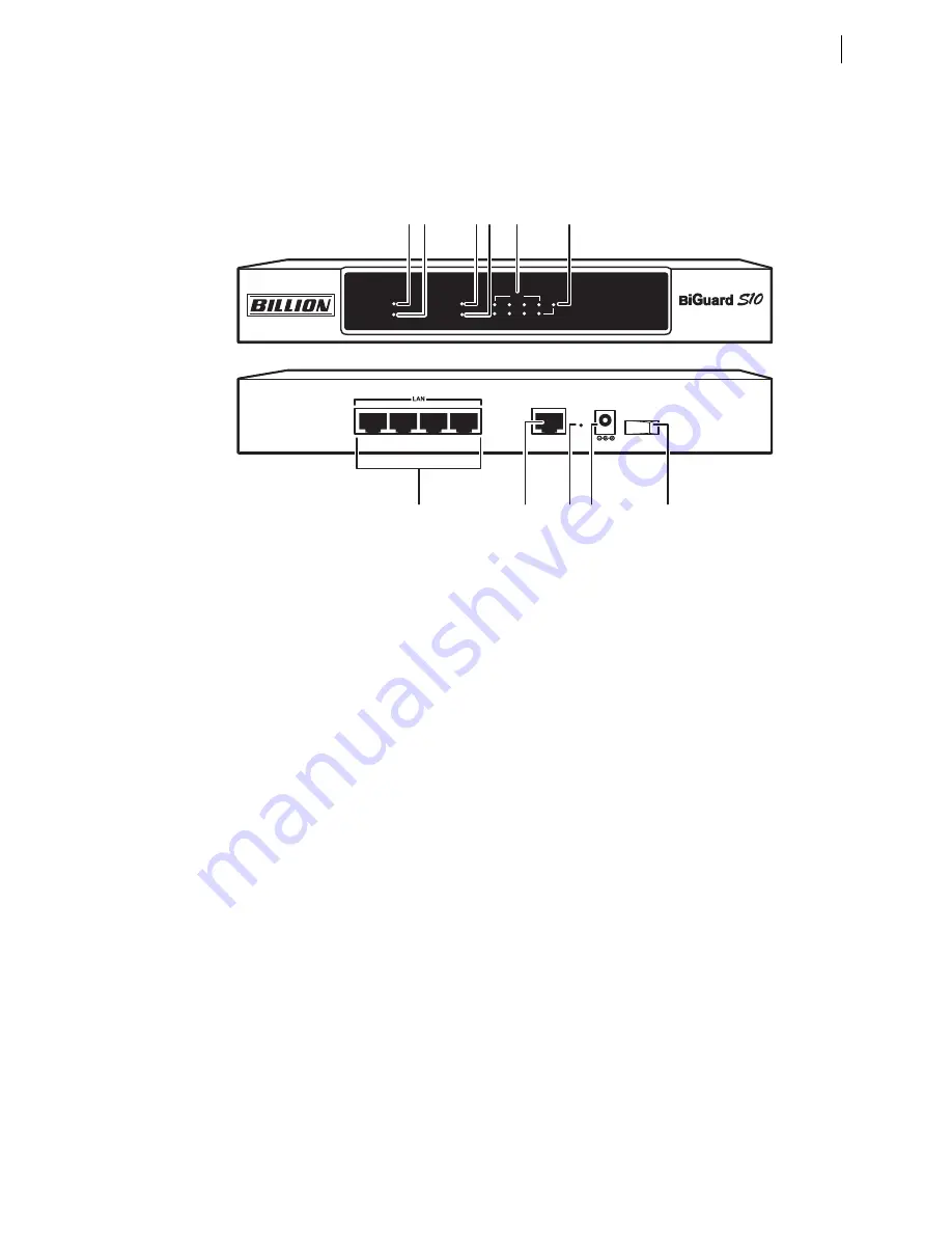
Front and rear view of the BiGuard S10
19
Front and rear view of the BiGuard S10
Figure 1
shows the front and rear components on the BiGuard S10.
FIGURE 1
B
I
G
UARD
S10
FRONT
AND
REAR
VIEWS
Setting up the BiGuard S10
This section provides a step-by-step guide in the hardware setup (rackmounting and power con-
nection) and installation (LAN and WAN) of the BiGuard S10.
SYSTEM
WAN
LAN
1
2
3
4
DMZ
10/100M
iBusiness Security Gateway
Power
Status
Link/ACT
4
3
2
1
LAN
WAN
12V DC
OFF ON
RESET
1 2
3 4
6
5
7
8
9
10
11
1. Power LED
On: Power is turned on
2. Status LED
Blinking: Device is in use
3. WAN 10/100 LED
Green: Connected at 100 Mbps
Off: Connected at 10 Mbps
4. LINK/ACT LED
On: Corresponding port (on rear) is
connected
Blinking: Data is being transmitted or
received
5. LAN 1~4 LEDs
10/100M
Green: Connected at 100 Mbps
Off: Connected at 10 Mbps
LINK/ACT
On: Corresponding port (on rear) is
connected
Blinking: Data is being transmitted or
received
6. DMZ LED
On: DMZ is enabled
7. ON/OFF switch
Turns the BiGuard S10 on or off
8. DC 12V connector
Connect the power adapter here
9. RESET button
Press to reset the BiGuard S10 to the
factory default settings.
10. WAN RJ-45 connector
10/100M autosensing Ethernet port
for xDSL/cable modem connection
11. LAN 1~4 RJ-45 connectors
Use UTP Ethernet cables (CAT5 or
CAT5e) to connect PCs to the net-
work.


