29
Installation, Operation and Maintenance Manual
MAN 571_EAC Rev. 1
September 2020
Operation and Use
Section 3: Operation and Use
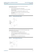
For the adjustment of the mechanical stop on the end flange of cylinder,
follow these steps (Figure 25):
•
Rem
ove with the specific wrench (c1) the plug (t).
•
Insert a wrench for Allen keys (c2) in the through hole until reaching the
adjustment pin (g).
•
Keep the protection cover blocked with the special wrench (c3).
•
Turn counter-clockwise to increase the angular stroke, turn clockwise
to decrease it.
•
When the adjustment is over tighten the plug (t).
Figure 25
Mechanical Stop of the Cylinder
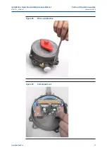
For the adjustment of the mechanical stop srewed into the left side of housing,
follow these steps (Figure 26 and 27):
•
Loosen the locknut (d) with the specific wrench (c2).
•
Adjust the pin (g)/screw (v) with the adequate wrench (c1).
•
Turn counter-clockwise to increase the angular stroke, turn clockwise
to decrease it.
•
When the adjustment is over tighten the locknut (d).
Figure 26
Mechanical Stop on the Housing


