UPSI-2412
Revision 1
17
F General Data
F1 Installation advice
Installation and operation of this device is only allowed to be executed by a qualified
electrician!
The application has to be separated from any power during the mounting process.
Wires have to be connected safely and must not have contact with sharp edges. Pay attention
to correct polarity! Before commissioning, check all the connections for correctness!
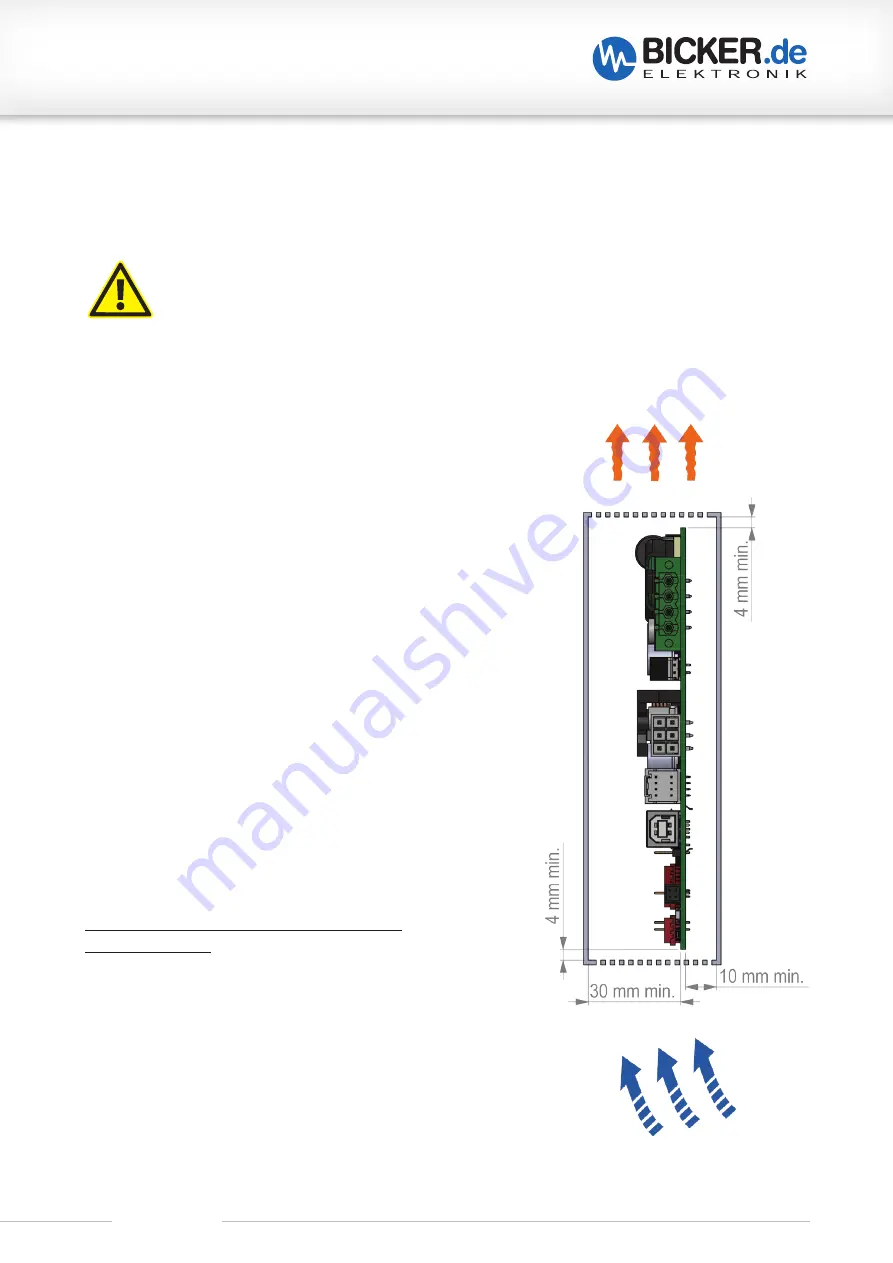
F2 Convection and installation position
When installing in the overall system, it has to be ensured that
the required distances to neighboring parts and boards are main-
tained.
Sufficient ventilation holes or open ventilation areas should
be provided during installation in order to avoid air congestion or
the like.
The device can optionally be installed in the system with
suitable heat conducting pads (gap pad / gap filler) in order to
compensate for temperature increases of the components due
to closer / narrow placement to neighboring components. This is
recommended on the bottom side in the area of the converter
(choke L1, MOSFETs Q3-Q6, Q39) and in the input area (choke L2).
The functional grounding of the UPSI-2412 is provided on the
input side (V
IN –
). So that the EMC filter on the circuit board can
work correctly, the output GND (V
OUT–
) should not be connec-
ted directly to the input GND (V
IN –
). The mounting hole next to
socket X1 is connected to V
IN –
, the remaining mounting holes are
isolated.
It is recommend, installing the board vertically in the overall
system with the input / output socket X1 pointing upwards. This
installation position favors the heat dissipation of the circuit board
hot spots in the area of X1 and the converter.
The following distances to neighboring devices
are recommended:
Top side circuit board:
–> Neighboring component: 30 mm min.
Bottom side circuit board:
–> Neighboring component: 10 mm min.
Left/right:
–> Neighboring component: 4 mm min.
Содержание UPSI-2412
Страница 3: ...UPSI 2412 Revision 1 3...


