


UPSI-2412
Revision 1
19
F4 Description of connectors
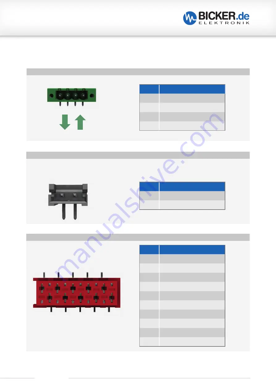
INPUT AND OUTPUT (X1)
PIN
FUNCTION
1
Vin +
2
Vin –
3
Vout –
4
Vout +
V
in
V
out
+
– –
+
4
3 2
1
PIN
FUNCTION
1
+5 V (50 mA max.)
2
DSR
3
RXD
4
NC
5
TXD
6
NC
7
DTR
8
NC
9
GND
10
NC
RS-232 (X5)
1 3 5 7 9
2 4 6 8 10
PIN
FUNCTION
1
Relay contact 1
2
Relay contact 2
2
1
The function of the relay connection is configurable via software. When closing the relay the resistor
value between both contacts is approx. 0 Ω, otherwise they are „open load“.
RELAY (X6)
Содержание UPSI-2412
Страница 3: ...UPSI 2412 Revision 1 3...


