BFT MOOVI 30 RMM Скачать руководство пользователя страница 21

INSTALLATION MANUAL

ENGLISH

- Rapid closing (

D?QRAJQ

 ) [ OFF ]  

ON:  Closes  barrier  after  photocell  disengagement,  before  waiting  for  

the end of the TCA (automatic closing time) set.

OFF:  Command not entered.

- SCA Alarm (

1!?J?PK

) [ ON ]

ON:   The SCA contact (terminals 12-13) behaves as follows:
 

with barrier open and on opening:...contact closed (warning light on)


with barrier closed:contact open.........................(warning light off)


on closing:........................................ intermittent contact (blinking) 

OFF:  The SCA contact closes according to the modes set by the Alarm 

Time parameter. 

-   Master/Slave  (

+?QRCP

) [ OFF ]

ON:  The control panel is set as Master in a centralised connection (see 

Paragraph 7). 

OFF:  The control panel is set as Slave in a centralised connection (see 

Paragraph 7).

-   Photocell test (

RCQRNFMR

) [ OFF ] 

ON:  Activates photocell check (see Fig. 3)
OFF:  Deactivates photocell check

-   Electric edge test (

RCQR@?P

) [ OFF ]

ON:  Activates electric edge check (see Fig. 3)
OFF:  Deactivates electric edge check

-    Fixed code (

DGVCBAMBC

) [ OFF ]

ON:  The receiver is configured for operation in fixed-code mode, see 

paragraph on “Radio Transmitter Cloning”.

OFF:  The receiver is configured for operation in rolling-code mode, see 

paragraph on “Radio Transmitter Cloning”.

-    Radio transmitter programming  (

P?BGMNPME

) [ ON ]

ON:  This enables transmitter storage via radio:
 

1 – First press the hidden key (P1) and then the normal key (T1, 
T2, T3 or T4) of a transmitter already  memorised in standard mode 
by means of the radio menu.


2 – Within 10s press the hidden key (P1) and the normal key (T1, 
T2, T3 or T4) of a transmitter to be memorised.


The  receiver  exits  the  programming  mode  after  10s,  other  new 
transmitters can be entered before the end of this time. 


This mode does not require access to the control panel.

OFF:  This disables transmitter storage via radio.
 

The  transmitters  can  only  be  memorised  using  the  appropriate 
Radio menu.

12.3) Radio Menu (

P?BGM

)  

-   Add start (

?BBQR?PR

)


Associates the required key to Start command

-   Read  (

PC?B

  Checks one key of a receiver; if stored it displays a message showing 

the receiver number in the memory location (from 01 to 64), and the 
key number (T1, T2, T3 or T4).

-   Eliminate list  (

CPC?QC

)

  WARNING!

 Completely removes all memorised radio control devices 

from the receiver memory. 

Receiver code reading

 (

06AMBC

)

  This displays the code entered in the receiver.

12.4) Language Menu (

*?LES?EC

)

Allows you to set the language on the display programmer.
5 languages are available:

-   ITALIAN (

2

-   FRENCH (

$0

-   GERMAN (

"#3

)

-   ENGLISH (

#,%

-   SPANISH (

#1.

12.5) MENU DEFAULT (

"#$3*2

)

Restores the preset default values on the control unit. After restoring, a 
new autoset operation must be carried out. 

12.6) DIAGNOSTICS AND MONITORING

The display on the 

LEO MV D

 panel shows some useful information, both 

during normal operation and in the case of malfunctions.

Diagnostics:

In the case of malfunctions, the display shows a message indicating which 
device needs to be checked:
STRT  

= START 

input activation

STOP 

= STOP input activation

PHOT 

= PHOT input activation

FLT   

= FAULT input activation for checked photocells 

SWO 

= input activation OPENING LIMIT SWITCH

SWC 

= input activation CLOSING LIMIT SWITCH

OPEN 

= OPEN input activation

CLS 

= CLOSE input activation

BAR 

= input activation SAFETY EDGE

TIME 

= TIMER input activation

In the case where an obstacle is found, the 

LEO MV D

 panel stops the 

door and activates a reverse manoeuvre; at the same time the display 
shows the “BAR” message.

12.7) Statistics

Having connected the 

Universal palmtop programmer

 to the control unit, 

enter the CONTROL UNIT / STATISTICS menu and scroll the screenful 
showing the statistical parameters:
-  Board microprocessor software version.
-  Number of cycles carried out. If motors are replaced, count the number 

of manoeuvres carried out up to that time. 

-  Number of cycles carried out from the latest maintenance operation. 
 

It is automatically set to zero after each self-diagnosis or parameter writ-
ing. 

-  Date of latest maintenance operation. To be updated manually from 

the appropriate menu “Update maintenance date”.

-  Installation description. 16 characters can be entered for installation 

identification.

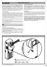
13) CONNECTION TO PARKY CAR-PARK MANAGEMENT SYSTEM

The board is provided with an output (terminal JP4) for controlling the 
barrier status, configured as follows (Fig.22):
contact 

closed

 between terminals 

19 and 20

 with barrier 

lowered

contact 

closed

 between terminals 

18 and 20 

with barrier 

raised

.

14) SERIAL CONNECTION USING SCS1 BOARD (Fig.21) 

The 

LEO-MV-D

 control panel allows several automation units (SCS1) to 

be connected in a centralised way by means of appropriate serial inputs 
and outputs. This makes it possible to use one single command to open 
and close all the automation units connected.
Following the diagram in Fig.21, proceed to connecting all the 

LEO-MV-D


control panels, exclusively using a telephone-type line. 
Should a telephone cable with more than one pair be needed, it is indis-
pensable to use wires from the same pair.
The length of the telephone cable between one appliance and the next 
must not exceed 250 m.
At this point, each of the 

LEO-MV-D

 control panels must be appropriately 

configured, by setting a MASTER unit first of all, which will have control 
over all the others, to be necessarily set as SLAVE (see logic menu).
Also set the Zone number (see parameter menu) between 0 and 127. 
The zone number allows you to create groups of automation units, each 
one answering to the Zone Master unit. 

Each zone can only be assigned 

one Master unit, the Master unit in zone 0 also controls the Slave 

units in the other zones.

14.1) Opposite Barriers (Fig.21A)

Only with 3.7 or later microprocessor version. 

By means of a serial connection, it is also possible to obtain centralised 
control of two opposite barriers/gates.
In  this  case,  the  Master  M1  control  panel  will  simultaneously  manage 
closing and opening for the Slave M2 control panel.
SETTING REQUIRED FOR OPERATION:
- MASTER board: 

XMLC

=128, 

K?QRCP

=ON

- SLAVE board: 

XMLC

=128, 

K?QRCP

=OFF

WIRING REQUIRED FOR OPERATION:
- The MASTER and SLAVE control units are interconnected through the 

4 wires (RX/TX) for the SCS1 interface boards;

- All the activation controls, as well as the remote controls must refer to 

the MASTER board;

- All  the  photocells  (checked  or  unchecked)  must  be  connected  to  the 

MASTER control panel;

- The safety edges (checked or unchecked) of the MASTER leaf must be 

connected to the MASTER control unit;

- The safety edges (checked or unchecked) of the SLAVE leaf must be 

connected to the SLAVE control unit.


15) LIMIT SWITCH SETTING

WARNING: before opening the door, make sure that the spring has 

been unloaded (rod at 43°).

 The barrier is provided with electrical limit 

switches and end-of-stroke mechanical stop devices. There must be a 
rotation margin (about 1°) on closing and opening between the electrical 
limit switches and mechanical stop devices (fig.11). The adjustment is 
carried out as follows:
-  Activate the manual release, bring the bar to its completely open posi-

tion (perfectly vertical).

-   Manually  advance  the  bar  by  about  2°  with  respect  to  the  vertical 

position.

MOOVI 30S-30RMM-50RMM  Ver. 05 

-

 21

D811480_05

Содержание MOOVI 30 RMM

Страница 1: ...E FOR VEHICULAR BARRIERS AUTOMATISME ELECTROMECANIQUE POUR BARRIERE POUR VÉHICULES ELEKTROMECHANISCHER ANTRIEB FÜR FAHRZEUGSCHRANKEN AUTOMATISMOS ELECTROMECANICOS PARA BARRÉRAS VEHICULAR AUTOMATIZAÇÃO ELECTROMECÂNICA PARA BARREIRA VEICULAR 8 027908 283818 ISTRUZIONI D USO E DI INSTALLAZIONE INSTALLATION AND USER S MANUAL INSTRUCTIONS D UTILISATION ET D INSTALLATION INSTALLATIONS UND GEBRAUCHSANLEI...

Страница 2: ...2 MOOVI 30S 30RMM 50RMM Ver 05 D811480_05 ...

Страница 3: ...i I pedoni non devono transitare nell area di manovra dell automazione Prevedere un apposito pas saggio pedonale 2 SBLOCCO DI EMERGENZA Fig 1 Lo sblocco di emergenza rende l asta manovrabile manualmente Si attiva dall esterno del cassone inserendo la chiave personalizzata nella serratura posta sotto l asta stessa e ruotandola di 180 in senso antiorario ATTENZIONE Nel caso necessiti attivare lo sbl...

Страница 4: ...estrians must not walk within the operator manoeuvring area An appropriate pedestrian passageway must be provided for 2 EMERGENCY RELEASE Fig 1 The emergency release allows the bar to be manoeuvred manually It is activated from the outside of the box by inserting the personalised key into the lock placed under the bar and rotating it anticlockwise by 180 WARNING When an actuator without bar needs ...

Страница 5: ...forations ATTENTION La barrière doit être exclusivement utilisée pour le passage des véhicules Les piétons ne doivent pas passer dans l aire de manoeuvre de l automation Prévoir un passage piétons spécial 2 DEVERROUILLAGE D URGENCE Fig 1 Le déverrouillage d urgence permet de manoeuvrer manuellement lisse On l active de l extérieur du caisson en enfonçant la clé personnalisée dans la serrure située...

Страница 6: ...rfen den Aktionsbereich der Anlage nicht passieren Für sie ist deshalb ein eigener Fußgän gerweg vorzusehen 2 NOTENTRIEGELUNG Abb 1 Die Notentriegelung ermöglicht es den Schrankenbaum von Hand zu be wegen Sie wird von außen am Schrankengehäuse aktiviert indem der im Lieferumfang enthaltene Schlüssel in das Schloß unterhalb des Balkens eingeführt und um 180 gegen den Uhrzeigersinn gedreht wird ACHT...

Страница 7: ...vehículos Los peatones no deben transitar en el área de maniobra del automatismo Es necesario prever un pasaje peatonal específico 2 DESBLOQUEO DE EMERGENCIA Fig 1 El dispositivo de desbloqueo de emergencia permite maniobrar el asta a mano Se activa desde fuera de la caja insertando la llave personalizada en la cerradura colocada bajo el asta y dándole una vuelta de 180 en sentido contrario a las ...

Страница 8: ...ansitar pela zona demanobradoautomatismo Preverumapassagemespecificadamente para peões 2 DESBLOQUEIO DE EMERGÊNCIA Fig 1 O desbloqueio de emergência consente de manobrar manualmente a haste Activa se do exterior da caixa metálica inserindo a chave personalizada na fechadura colocada por baixo da haste e girando a de 180 no sentido contrário aos ponteiros do relógio ATENÇÃO Caso seja necessário act...

Страница 9: ...ché dalle deformazioni che potrebbero verificarsi durante l uso L installazione deve essere in accordo con quanto previsto dalle Diret tive Europee 89 336 CEE 73 23 CEE 98 37 CEE e loro modifiche successive Togliere l alimentazione elettrica prima di qualsiasi intervento sull im pianto Scollegare anche eventuali batterie tampone se presenti Prevedere sulla rete di alimentazione dell automazione un...

Страница 10: ...ella posizione fig 4 rif Dx con la vite e il dado autobloccante I Regolare il tendimolla fig 4 rif 2 fino a mettere in tensione la molla L Rimontare e fissare parzialmente il cavallotto fig 4 rif 4 che fissa l asta all attuatore in posizione di apertura M L installazione del Kit anticesoiamento MOOVI PRM opzionale risulta più agevole se effettuata prima del montaggio dell asta sull automazio ne Fa...

Страница 11: ...trici CEI 64 8 IEC364 armonizzazione HD384edaltrenormenazionali Tenerenettamenteseparatiicollegamenti di alimentazione di rete dai collegamenti di servizio fotocellule coste sensibili dispositivi di comando ecc ATTENZIONE Per il collegamento alla rete utilizzare cavo multipo lare di sezione minima 3x1 5mm2 e del tipo previsto dalle normative precedentemente citate a titolo di esempio se il cavo no...

Страница 12: ...spazio di rallentamento in apertura e chiusura desiderato tra 1 e 90 NOTA Alla prima manovra ed a ogni mancanza di rete reset o sblocco manualedelcancello ilquadrocomandoesegueunamanovracompleta a velocità ridotta per apprendere la misura della corsa 3 Tempo allarme 2 JJ 30s Trascorso il tempo impostato variabile da 10s a 240s in caso di rile vamento ostacolo o di impegno delle fotocellule si chiu...

Страница 13: ...eda è dotata di una uscita morsetto JP4 per il controllo dello stato della barriera così configurato Fig 22 contatto chiuso tra i morsetti 19 20 a barriera abbassata contatto chiuso tra i morsetti 18 20 a barriera alzata 14 CONNESSIONE SERIALE MEDIANTE SCHEDA SCS1 Fig 21 Il quadro di comando LEO MV D consente tramite appositi ingressi e uscite seriali SCS1 la connessione centralizzata di più autom...

Страница 14: ...uminio plastica ecc 21 SMANTELLAMENTO ATTENZIONE prima di aprire lo sportello la molla deve essere sca rica asta a 43 Nel caso l automazione venga smontata per essere poi rimontata in altro sito bisogna Togliere l alimentazione e scollegare tutto l impianto elettrico Togliere l attuatore dalla base di fissaggio Smontare tutti i componenti dell installazione Nel caso alcuni componenti non possano e...

Страница 15: ...MOOVI 30S 30RMM 50RMM Ver 05 15 D811480_05 ...

Страница 16: ...16 MOOVI 30S 30RMM 50RMM Ver 05 D811480_05 ...

Страница 17: ...well as from any deformation which might occur during use The installation must comply with the provisions set out by the follow ing European Directives 89 336 CEE 73 23 EEC 98 37 EEC and subsequent amendments Disconnect the electrical power supply before carrying out any work on the installation Also disconnect any buffer batteries if fitted Fit an omnipolar or magnetothermal switch on the mains ...

Страница 18: ...ring the release key fig 6 to the manual operation position and manually rotate the lever fig 4 ref 6 downwards by 90 fig 7 so as to bring the barrier to the right hand opening position H Lock the spring stretcher fig 4 ref 2 into position fig 4 ref Dx with the screw and self locking nut I Adjust the spring stretcher fig 4 ref 2 until the spring comes under tension L Refit and partially fix the U ...

Страница 19: ...ing must never be reduced to a pack be totally compressed Fig 9 indicates the position where the minimum value of the compressed spring is measured with the rod in the opening vertical bar position INSTALLATION MANUAL ENGLISH 8 ELECTRICAL INSTALLATION SET UP WARNING before opening the door make sure that the spring has been unloaded rod at 43 Set up the electrical installation fig 10 with referenc...

Страница 20: ... brackets 0 The writing appearing on the display is indicated between round brackets Refer to Figures A and B for the control unit configuration procedure 12 1 Parameter Menu 0 1 Automatic Closing Time 2 10s Set the numerical value of the automatic closing time from 1 to 180 seconds 2 Slow down Distance K P JJ 5 Set the required slow down distance for opening and closing between 1 and 90 NOTE powe...

Страница 21: ...e control unit enter the CONTROL UNIT STATISTICS menu and scroll the screenful showing the statistical parameters Board microprocessor software version Number of cycles carried out If motors are replaced count the number of manoeuvres carried out up to that time Number of cycles carried out from the latest maintenance operation It is automatically set to zero after each self diagnosis or parameter...

Страница 22: ...e mains power supply and require the assistance of a specialised tech nician installer When automation is out of order activate the emergency release see paragraph 11 so as torelease the manual bar opening and closing operations 20 SCRAPPING Materials must be disposed of in conformity with the current regula tions In case of scrapping the automation devices do not entail any particular risks or da...

Страница 23: ...MOOVI 30S 30RMM 50RMM Ver 05 23 D811480_05 ...

Страница 24: ...24 MOOVI 30S 30RMM 50RMM Ver 05 D811480_05 ...

Страница 25: ...e non respect des rè gles de bonne technique dans la construction des fermetures portes portails etc ainsi qu en cas de déformations pouvant se produire pendant l utilisation L installation doit être conforme aux prescriptions des Directives Européennes 89 336 CEE 73 23 CEE 98 37 CEE et modifications successives Couper l alimentation électrique avant d effectuer n importe quelle in tervention sur ...

Страница 26: ...tourner manuellement le levier fig 4 réf 6 vers le bas pour 90 fig 7 de telle façon àporter la barrière en position d ouverture droite H Bloquer le tendeur de ressort fig 4 réf 2 dans la position fig 4 réf Dx avec la vis et l écrou àblocage automatique I Régler le tendeur de ressort fig 4 réf 3 jusqu àtendre le ressort L Remonter et fixer partiellement le crampillon fig 4 réf 4 qui fixe la lisse a...

Страница 27: ...minimale que le ressort comprimé peut atteindre avec la lisse en position d ouverture verticale MANUEL D INSTALLATION FRANÇAIS 8 PREDISPOSITION DE L INSTALLATION ELECTRIQUE ATTENTION avant d ouvrir la porte le ressort doit être déchargé lisse à 43 Prédisposer l installation électrique fig 10 en se référant aux normes en vigueur pour les installations électriques CEI 64 8 IEC364 har monisation HD38...

Страница 28: ...valeur étant exprimée en centaines pendant les cent premières manœuvres l écran indique toujours 0000 Nombre de commandes radio mémorisées Un appui sur la touche OK pendant la phase de présentation initiale permet de passer directement au premier menu paramètres Nous fournissons de suite une liste des menus principaux avec les cor respondants sous menus disponibles Le paramètre prédéfini est celui...

Страница 29: ...quant quel est le dispositif qu il faut vérifier START activation entrée START STOP activation entrée STOP PHOT activation entrée PHOT SWO activation de l entrée FIN DE COURSE POUR L OUVERTURE SWC activation de l entrée FIN DE COURSE POUR LA FERMETURE OPEN activation entrée OPEN CLS activation entrée CLOSE BAR activation de l entrée BARRE PALPEUSE TIME activation entrée TIMER Silevantailrencontreu...

Страница 30: ...ues Les nettoyer de temps en temps Barre palpeuse Contrôler périodiquement que la barre palpeuse arrête la lisse en cas d obstacle Tous les deux ans démonter le motoréducteur et vidanger la graisse lubrifiante Pour toute anomalie de fonctionnement non résolue couper l alimenta tion de ligne et demander l intervention de personnel qualifié instal lateur Pendant la période de hors service de l autom...

Страница 31: ...DGL DGL MOOVI 30S 30RMM 50RMM Ver 05 31 D811480_05 ...

Страница 32: ...DGL DGL DGL 32 MOOVI 30S 30RMM 50RMM Ver 05 D811480_05 ...

Страница 33: ...er Hersteller lehnt jede Verantwortung für Folgen ab die durch nicht fachgerechteAusführungenvonSchließvorrichtungen Türen Toreusw oder durch Verformungen während des Betriebes entstehen Die Montage muß im Einklang mit folgenden Europäischen Richtlinien erfolgen 89 336 EWG 73 23 EWG 98 37EWG und nachfolgende Än derungen Vor jedem Eingriff an der Anlage die Stromversorgung unterbrechen Auch Pufferb...

Страница 34: ...en Hebel Abb 4 Pos 6 um 180 drehen und auf ein richtiges Einrasten achten F Die Zugstange Abb 4 Pos 5 welche den Hebel Abb 4 Pos 6 festhält mit einem Drehmomentschlüssel und einer Einstellung von ca 80 Nm festziehen G Den Entriegelungsschlüssel Abb 6 in die Stellung für den Handbetrieb bringen und den Hebel Abb 4 Pos 6 mit der Hand nach unten auf 90 Abb 7 drehen sodaß die Schranke in die Stellung ...

Страница 35: ...ie Notentriegelung aktivieren Abb 14 Den Schrankenbaum auf etwa 45 positionieren Abb 9 Er muss diese Stellung beibehalten Wenn der Balken MONTAGEANLEITUNG DEUTSCH zum Öffnen neigt die Feder durch Betätigung der Zugstange T entspan nen Wenn der Balken zum Schließen neigt die Feder durch Betätigung der Zugstange T spannen In beiden Fällen die Feder soweit spannen oder entspannen bis der Balken bei e...

Страница 36: ...artungstermin in Hundert sodaß auf dem Bildschirm vor Erreichen der ersten Hunderte Betriebs vorgänge 0000 steht Zahl der gespeicherten Fernsteuerungen Drückt man während der anfänglichen Präsentationsphase OK so wechselt man direkt zum ersten Menü Parameter Nachstehend werden die Hauptmenüs mit den zugehörigen Untermenüs aufgeführt In eckigen Klammern steht die Vorbesetzung 0 In runden Klammern w...

Страница 37: ...splay auf der Steuerung LEO MV D stellt sowohl im Normalbetrieb als auch im Störungsfall einige nützliche Informationen bereit Diagnostik Bei Auftreten von Störungen erscheint auf dem Display eine Meldung mit der Angabe welche Vorrichtung geprüft werden muß STRT Aktivierung Eingang START STOP Aktivierung Eingang STOP PHOT Aktivierung Eingang PHOT SWO Aktivierung Eingang ENDSCHALTER ÖFFNUNG SWC Akt...

Страница 38: ...nigen Sicherheitsleiste In bestimmten Zeitabständen von Hand nachprüfen ob die Leiste den Schrankenbaum bei Auftreten eines Hindernisses stoppt Alle zwei Jahre den Getriebemotor auseinanderbauen und das Schmierfett wechseln Bei jeder auftretenden und nicht behobenen BetriebsstörungdieStromversorgungunterbrechenundFachpersonalhinzu ziehen Installationstechniker Für die Zeit in der die Anlage außer ...

Страница 39: ...MOOVI 30S 30RMM 50RMM Ver 05 39 D811480_05 ...

Страница 40: ...40 MOOVI 30S 30RMM 50RMM Ver 05 D811480_05 ...

Страница 41: ...omo de las deformaciones que se podrían verificar durante el uso La instalación debe ser conforme a lo previsto por las siguientes Direc tivas Europeas 89 336 CEE 73 23 CEE 98 37 CEE y modificaciones sucesivas Cortar el suministro de corriente antes de efectuar cualquier intervención en la instalación Desconectar también eventuales baterías tampón si las hay Prever en la red de alimentación del au...

Страница 42: ... 6 hacia abajo dándole una vuelta de 90 fig 7 para colocar la barrera en posición de apertura derecha H Bloquear el tensor de muelles fig 4 ref 2 en la posición fig 4 ref Dx con el tornillo y la tuerca autobloqueante I Regular el tensor de muelles fig 4 ref 2 hasta que el muelle quede tenso L Montar de nuevo y fijar parcialmente el perno de U fig 4 ref 4 que fija el asta al servomotor en posición ...

Страница 43: ...ebe comprimirse nunca completamente En la fig 9 está indicada la posición para determinar la medida mínima que puede alcanzar el muelle comprimido con el asta en posición de apertura vertical MANUAL DE INSTALACIÓN ESPAÑOL 8 PREDISPOSICION DE LA INSTALACION ELECTRICA ATENCIÓN antes de abrir la puertezuela se debe descargar el resorte astaa43 Hayquepredisponerlainstalacióneléctrica fig 10 observando...

Страница 44: ...cipales y los correspondientes submenús disponibles El parámetro predefinido es el que aparece entre paréntesis cuadrados 0 Entre paréntesis redondos se indica la palabra que aparece en el dis play Véanse las Figuras A y B para el procedimiento de configuración de la central 12 1 Menú Parámetros 0 1 Tiempo Cierre Automático 2 10s Hayqueconfigurarnuméricamenteelvalordeltiempodecierreautomático de 1...

Страница 45: ...P activación entrada STOP PHOT activación entrada PHOT SWO activación entrada FIN DE CARRERA DE APERTURA SWC activación entrada FIN DE CARRERA DE CIERRE OPEN activación entrada OPEN CLS activación entrada CLOSE BAR activación entrada BARRA SENSIBLE TIME activación entrada TIME En caso de que la hoja encuentre un obstáculo el cuadro LEO MV D de tiene la hoja y activa una inversión simultáneamente e...

Страница 46: ...os sistemas de accionamiento véanse las instrucciones correspondientes 19 MANTENIMIENTO ATENCIÓN antes de abrir la puertezuela se debe descargar el resorte asta a 43 ATENCION Antes de realizar cualquier operación de man tenimiento en la instalación es preciso cortar el suministro de corriente al automatismo Los puntos que necesitan controles y mantenimiento son Las lentes de las fotocélulas Es pre...

Страница 47: ...Fig A DGLC DGLC MOOVI 30S 30RMM 50RMM Ver 05 47 D811480_05 ...

Страница 48: ...Fig B DGLC DGLC DGLC 48 MOOVI 30S 30RMM 50RMM Ver 05 D811480_05 ...

Страница 49: ...icarse durante o uso A instalação deve estar de acordo com quanto previsto pelas Directivas Europeias 89 336 CEE 73 23 CEE 98 37 CEE e modificações suces sivas Interrompa a alimentação eléctrica antes de qualquer intervenção na instalação Desligue também eventuais baterias compensadoras se presentes Instale na rede de alimentação da automatização um interruptor ou um magnetotérmicoomnipolarcomdist...

Страница 50: ...gulada a um binário de cerca 80 Nm G Coloque a chave de desbloqueio fig 6 na posição de funcionamento manual e gire manualmente a alavanca fig 4 ref 6 para baixo de 90 fig 7 de maneira a colocar a barreira na posição de abertura direita H Bloqueie o tensor da mola fig 4 ref 2 na posição fig 4 ref Dx com o parafuso e a porca de autobloqueio I Regule o tensor da mola fig 4 ref 2 até colocar a mola s...

Страница 51: ...rimir se completamente Na fig 9 está indicada a posição da medida mínima que pode alcançar a mola comprimida com a haste na posição de abertura vertical MANUAL PARA A INSTALAÇÃO PORTUGUÊS 8 PREDISPOSIÇÃO DA INSTALAÇÃO ELÉCTRICA ATENÇÃO antes de abrir a portinhola a mola tem que estar des carregada haste a 43 Prepare a instalação eléctrica fig 10 fazendo referência às normas vigentes para instalaçõ...

Страница 52: ...nte 0000 Número de radiocomandos armazenados Uma pressão da tecla OK durante a fase de apresentação inicial consente de passar directamente para o primeiro menu parâmetros A seguir estão indicados os menus principais e os relativos submenus disponíveis O parâmetro predefinido é o fechado entre parênteses quadrados 0 Entre parênteses redondos está indicada a escrita que aparece no visor Tomar como ...

Страница 53: ...E BAR activação da entrada PERFIL SENSÍVEL TIME activação da entrada TIME No caso em que a folha encontre um obstáculo o quadro LEO MV D pára e comanda uma inversão e ao mesmo tempo o visor visualiza a mensa gem BAR 12 7 Estatísticas UmavezligadooProgramadorpalmaruniversalàcentral entrenomenuCEN TRAL ESTATÍSTICAS e desloque o ecrã dos parâmetros estatísticos Versão software microprocessador placa ...

Страница 54: ...te no caso de obstáculo A cada dois anos desmonte o motoredutor e substitua a massa lubrificante Para qualquer anomalia de funcionamento que tenha sido encontrada e não resolvida interrompa a alimentação e peça a intervenção de pessoal qualificado instalador Para o período em que a automatização estiver fora de serviço active o desbloqueio de emergência vide parágrafo 11 de modo a tornar livre a a...

Страница 55: ...DGLC DGLC MOOVI 30S 30RMM 50RMM Ver 05 55 D811480_05 ...

Страница 56: ...DGLC DGLC DGLC 56 MOOVI 30S 30RMM 50RMM Ver 05 D811480_05 ...

Страница 57: ...Fig 3 Fig 1 Fig 2 500 600 400 500 20 350 400 22 cm 38mm 5m Moovi 50 RMM 3m Moovi 30S RMM 32 cm 80 cm 70mm 100 cm 7 10 4 8 9 5 11 6 MOOVI 30S 30RMM 50RMM Ver 05 57 D811480_05 ...

Страница 58: ...Fig 7 Fig 5 Fig 6 Fig 4 1 2 6 3 SX DX 80Nm 4 5 58 MOOVI 30S 30RMM 50RMM Ver 05 D811480_05 ...

Страница 59: ...MOOVI 30S 30RMM 50RMM Ver 05 59 D811480_05 ...

Страница 60: ...Fig 13 Fig 14 2 G C Fig 11 Fig 12 SWC SWO SWC SWO 60 MOOVI 30S 30RMM 50RMM Ver 05 D811480_05 ...

Страница 61: ...CBO MOOVI GA MOOVI GAMA MOOVI130 MOOVI PCA MOOVI LIGHT PRM 2 3 7 8 P L P D C D C 6 4 SX 2 5 DX 1 2 Left Gauche Links Izquierda Esquerda 1 Right Droite Rechts Derecha Direita MOOVI 30S 30RMM 50RMM Ver 05 61 D811480_05 ...

Страница 62: ...62 MOOVI 30S 30RMM 50RMM Ver 05 D811480_05 ...

Страница 63: ...MOOVI 30S 30RMM 50RMM Ver 05 63 D811480_05 ...

Страница 64: ...64 MOOVI 30S 30RMM 50RMM Ver 05 D811480_05 ...

Страница 65: ...Fig 22 Fig 23 JP4 18 19 20 NO NC COM JP4 18 19 20 NO NC COM SLM2 C D E LAMPO PA Fig 24 A CELLULA130 B MOOVI130 A CELLULA130 B MOOVI130 F G MOOVI 30S 30RMM 50RMM Ver 05 65 D811480_05 ...

Страница 66: ...ida Instalação não consentida BIR Costa Sensibile Safety edge Barre palpeuse Sicherheitsleiste Barra sensible SB Solo per MOOVI 30 50 Only for MOOVI 30 50 Uniquement pour le modèle MOOVI 30 50 nur für MOOVI 30 50 Únicamente para MOOVI 30 50 Somente para MOOVI 30 50 A 3 0 3 2 3 4 3 6 3 8 4 0 4 2 4 4 4 6 4 8 5 0 L m kg m MOOVI 50 RMM 1 30 1 40 1 50 1 60 1 10 1 00 1 20 1 70 1 80 1 90 2 00 2 10 2 20 2...

Страница 67: ...MOOVI 30S 30RMM 50RMM Ver 05 67 D811480_05 ...

Страница 68: ......

Отзывы: