background image

LB 571 BTwave 

6 Start up and Calibration 


68847BA2 Rev.00, 10/2020 

21


6


Start up and Calibration 

When resonator is powered up (24VDC/10A) and USB/RS422 adapter is connected 
to the PC, device can be operated by using the UI software. 

6.1


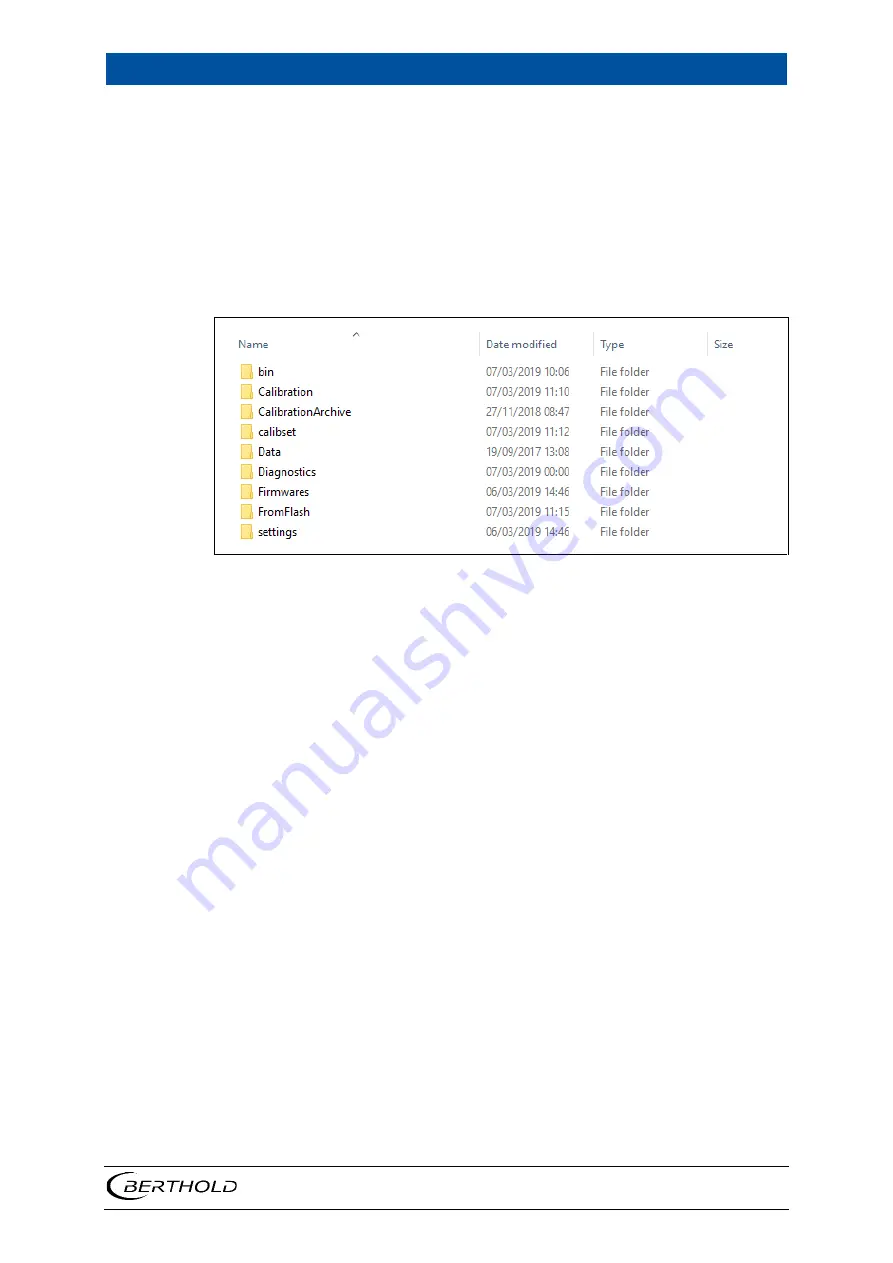
UI folder structure 


Figure 8  UI folder structure 


Meaning of the above folders are as follows: 
 

Bin:


Executable UI and a General log-file. 

Calibration:


Sample files (*.OLC) stored on PC. 

CalibrationArchive: 

  Not used. 

Calibset:  


Calibrations stored on PC (*.XML). 

Diagnostics:


Measurement data –files stored on PC. 

Firmwares:


MCU firmware release. 

FromFlash:


 Stored sample (calib-xx.CSV) and online data (online-
xx.CSV) files, which have been downloaded from SD-card us-
ing the UI. 

Settings:


 Windows, device and recipe setting-files (parameters) 

stored on PC. 

 
More detailed information about these further in this document. 


Содержание BTwave LB 571-02

Страница 1: ...BTwave LB 571 02 Operating Manual 68847BA2 Rev No 00 01 2020 ...

Страница 2: ......

Страница 3: ...Berthold Technologies GmbH Co KG Calmbacher Str 22 75323 Bad Wildbad Germany www berthold com Phone 49 7081 177 0 Fax 49 7081 177 100 nuclear berthold com ...

Страница 4: ......

Страница 5: ...s 12 4 Installation 13 4 1 General Information 13 4 2 Unpacking Scope of Delivery 13 4 3 Environmental Conditions 13 4 4 Mounting of the System 14 5 Commissioning 15 5 1 Safety Instructions 15 5 2 Cables and wires 16 5 3 Electrical Connection 17 6 Start up and Calibration 21 6 1 UI folder structure 21 6 2 Setting up PC connection 22 6 3 Setting device parameters 24 6 4 Writing and reading product ...

Страница 6: ...tents LB 571 BTwave 2 68847BA2 Rev 00 10 2020 8 Error Codes and Alarms 41 8 1 Watchdog 41 8 2 Error codes 41 8 3 Alarm generation 42 8 4 Enabling alarms 42 9 Technical Information 45 10 Declaration of Conformity 47 ...

Страница 7: ...free to contact Berthold This document describes the B OMS resonator mechanical and electrical connec tions This also describes how to operate the device using the provided UI software Further information about device can be found in separate documents 1 2 Place of Storage These operating instructions as well as all relevant product related documentation for the respective application must be read...

Страница 8: ... be copied or reproduced in any form without the prior consent of the manufacturer 1 6 Convention Identification Meaning Example Quotation marks Field in the software user interface Calibrate Vertical line Path Settings Selection Angle brackets Keys and buttons Update Round brackets Graphic reference Attach the plug Fig 1 item 1 In the description of the software the term click is used to refer to...

Страница 9: ...i ous injury or death j WARNING Indicates a potentially hazardous situation which if not avoided could result in serious injury or death j CAUTION Indicates a potentially hazardous situation which if not avoided could result in moderate or minor injury or property damage NOTE Failure to observe this information can lead to disturbances in the sequence of operations and or damage to property IMPORT...

Страница 10: ... 1 9 Conformity Berthold declares at its sole responsibility that the design of this product as mar keted by Berthold conforms to the relevant EU directives stated in the original declaration of conformity see chapter 10Declaration of Conformity This declaration shall lose its validity if the product is modified without prior con sultation with Berthold ...

Страница 11: ...d Failure to observe the safety instructions and information on operation maintenance and disposal provided in the operating instructions Failure to observe the operating instructions for the delivered products Use under terms and conditions other than those stated by the manufac turer in their technical documentation data sheets operating and installation manuals and other specifications Use of t...

Страница 12: ...dealing with the device Trained persons Persons who through their technical training have acquired sufficient knowledge in the respective field and who are familiar with the relevant national industrial safety regulations accident prevention regulations guidelines and accepted engi neering standards Trained personnel must be able to safely assess the results of their work and be familiar with the ...

Страница 13: ...ics form one unit Analog output signal directly from the sensor 4 20 mA Digital inputs Several calibration curves Measuring range 0 30 moisture Temperature range 0 65 C 3 1 Overview An overview of the resonator with its external dimensions and connections are ex plained in this chapter Mechanical installation and depth adjustment of resonator is done by using a separate process installation flange...

Страница 14: ...y and quality factor of the resonator Both effects are measured and used as a direct indication of the moisture content The resonator consists of a ceramic disc which is embedded in a metal plate The upper side of the ceramic remains without a metal layer From this side the elec tromagnetic field interacts with the product to be measured The measured data are processed in the integrated evaluation...

Страница 15: ...e The resonator can be mounted on a conveyor belt for measurement The contact with the bulk material must be even and at a constant height Sliding plate For example the resonator can be installed under a silo on a material slide Screw conveyor The resonator can be attached to a tube of a screw con veyor by means of a flange NOTE With bulk goods that are transported by screw conveyor there is a pos...

Страница 16: ... Figure 4 and described with text below the figure 1 2 3 4 5 6 E480152 V1 1 Material temperature sensor assembly E48157 V1 0 USB RS422 adapter assembly connection for service laptop MicroSD card slot under cap Electronics and its interfaces under cover Supply voltage input 24 VDC I O cabling Figure 4 LB 571 External connections ...

Страница 17: ... to install the device The device are to be operated exclusively in a fixed installation 4 2 Unpacking Scope of Delivery The system is delivered with the appropriate components depending on the order Check that the delivery is complete and undamaged as ordered Immediately re port any missing defective or incorrect 4 3 Environmental Conditions j WARNING Danger due to installation in potentially exp...

Страница 18: ...rmissible ambient conditions in chapter 9 Technical Infor mation The device must be installed weatherproof The device must not be entered used as a climbing aid or used for any other purpose storage fixing point IMPORTANT The device must be mounted flat on the surface of the mounting device flange The operator is responsible for selecting the connection elements and tightening torque It is recomme...

Страница 19: ...n the housing in a dry environment and to carry out installation maintenance and repair work The measuring system the connected relay contacts and all inputs and out puts must be disconnected during installation and service work on the hardware and during cabling Only connect devices to the product that meet the applicable safety stand ards In case of electric shock carry out the required initial ...

Страница 20: ...inal body bare conductive parts of the cables e g wires of a stranded wire do not protrude from the terminal body the length of the ferrule or stripped wire is 8 mm so that the wire is held securely in the clamp all strands are pressed with a ferrule the conductor insulation extends into the collar of the ferrule the minimum permissible bending radii for the respective conductor cross section are ...

Страница 21: ...t of the resonator is 10 A NOTE Only components approved by Berthold may be used to commission the de vice 1 2 3 4 5 Hex socket screw M4x10 Locking washer Cover Cable gland cap nuts O ring seal Figure 6 Remove cover Tip For devices that are already in operation the cover of the housing can be diffi cult to remove Therefore loosen a cap nut of a cable gland to reduce the negative pressure 1 Loosen ...

Страница 22: ...in Assignment Figure 7 LB 571 Pin assignment 4 Make sure that all lines are correctly connected and routed 5 Tighten the cap nuts of the cable glands Figure 6 Pos 4 with a tightening torque of 5 5 Nm 6 Make sure there is a locking washer Figure 6 Pos 2 on each hex socket screw Figure 6 Pos 1 7 Make sure that the entire circumference of the O ring seal Figure 6 Pos 5 is undamaged and correctly inse...

Страница 23: ...6 GND Power input GND Supply voltage GND X8 Pin Name Colour Connection Comment 1 IOUT_1 supply Aout 1 4 20mA Moisture Passive Moisture to system 2 IOUT_1 load 3 IOUT_2 supply Aout 2 4 20mA Temperature Passive Material temperature to system 4 IOUT_2 load 5 D_IN_1_ Digital input 1 24VDC Sample button Sample button or digital input connection for sampling 6 D_IN_1_GND 7 D_IN_2_ Digital input 2 24VDC ...

Страница 24: ...5 Commissioning LB 571 BTwave 20 68847BA2 Rev 00 10 2020 ...

Страница 25: ...s are as follows Bin Executable UI and a General log file Calibration Sample files OLC stored on PC CalibrationArchive Not used Calibset Calibrations stored on PC XML Diagnostics Measurement data files stored on PC Firmwares MCU firmware release FromFlash Stored sample calib xx CSV and online data online xx CSV files which have been downloaded from SD card us ing the UI Settings Windows device and...

Страница 26: ...PC s USB port 2 Wait until PC has installed adapter drivers 3 Open Device Manager and check via which COM port device is accessible Figure 9 Device Manager COM ports 4 Power up resonator 24VDC 5 Open bin folder and double click BTwave 2 15 0 exe Figure 10 BTwave executable BTwave UI starts with an Online view Figure 11 BTwave UI Online view and maintenance pop up window ...

Страница 27: ... to Windows parameters 0 Address as found on Device Manager When value is changed text goes RED 11 Accept new value by clicking Enter button on PC and value turns YELLOW 12 Finally click Save to PC button 13 Restart UI and you should be connected See Figure 9 for successful connec tion Figure 8 shows an unsuccessful connection Figure 13 UI successful connection The following information of the dev...

Страница 28: ...time When connection to device is established next step is to set PC time to device It is explained below 1 Login as shown in chapter 4 2 2 Navigate to Diagnostics2 tab as shown on the next Figure Figure 15 Diagnostics2 tab 3 Click Set device time to PC time button 4 See that date and time below Set device time to PC time button has changed ...

Страница 29: ...nternal FLASH memory contents Parameters are never copied from SD card to FLASH memory Only the following parameters may need changes during start up And their meanings are as follows 3 Min_moisture Minimum moisture reading in given out by device Default 0 4 Max_moisture Maximum moisture reading in given out by device Default 100 5 AO1_I_min Analog output channel 1 minimum current output mA value ...

Страница 30: ...moisture reading in seconds 1 300 seconds Default 20 s 90 Temp_reg_hi C High limit for ceramic temperature control C Enter max product temperature Default 40 C 91 Temp_reg_low C Low limit for ceramic temperature control C Enter max product temperature 0 1 C Default 39 9 C 98 SD_card_detect Shows if SD card is inserted or not 0 no SD card inserted 1 SD card inserted This is a read only parameter on...

Страница 31: ... tab From the opened window sample list can be fetched by selecting Get sample list from SD card as shown on the Figure Figure 17 Read and selected calibration samples 6 6 Analog outputs control There are two analog outputs available AO1 Analog Out1 is controlled by filtered moisture value AO2 is controlled by filtered material temperature value There are totally 6 pa rameters related to each anal...

Страница 32: ...re starting with sampling please enssure that the SD card is inserted in the device To start taking samples go to Calibration tab shown on below figure and follow the steps shown below Figure 18 Taking samples 1 Click New sample 2 Below Moisture measurement view opens Figure 19 start sampling 3 Click Start button toggles to Stop and start collecting a sample for reference determination 4 When fini...

Страница 33: ...Below Read From SD card view opens except no samples shown Figure 20 Samples from SD card 3 Click Get sample list from SD card button and a list of all samples saved to SD card are shown as on above figure 4 Select samples by clicking the sample field marked X 5 Click Export selection to PC button and download starts 6 Finally click Close button and samples appear in the list of samples taken It i...

Страница 34: ...samples 1 Double click on a sample shown above and Calibration File view below opens where you can give additional information for the sample Figure 22 Save additional informationtion to sample file 2 Type reference value on Lab box 3 Type used product on ProductID box This is by default set to the product which has been active when sample was taken 4 Type comments on Additional Information box 5 ...

Страница 35: ...en reference values has been inserted device can be calibrated as explained below Figure 23 Calibration 1 Select samples X to be used in calibration as above 2 Click Calibrate button 3 Below autocalibrator view opens Figure 24 Calibration 4 Click the green Calibrate button marked with the arrow ...

Страница 36: ...whole moisture range is covered by the samples If material is quite homogenous and the whole moisture range is covered by the samples the parameter optimization may be used without the Polyfit The statistics for the calibration is shown in the bottom right corner These are as follows error RMSE Root Mean Square Error between the difference of Measured and Lab of the samples steyx Comparison betwee...

Страница 37: ...rial 1 parameters This is the saved calibration and its calculation parameters can be seen on the right side on the figure This calibration still needs to be activated to MCU as follows 9 Click Activate parameters button and below view opens Figure 27 Activate parameters 10 Add optional comments if needed and click Activate button and below view opens ...

Страница 38: ...ry of active Material 1 parameters 11 Finally click the blue Go to calibration button and the following view opens Figure 29 Recalculate samples 12 To have UI calculating new moisture values with the new parameters click Yes and samples are recalculated on Calibration tab Repeat these steps for the other materials products to be calibrated by using their product ID ...

Страница 39: ... calculated moisture content also shown on Mois ture graph red line raw and green line filtered temperature reading material and ceramic digital input line status I O and sensor error code generated by MCU By ticking Save to diagnostics log measurement data is stored to PC Diagnostics folder 7 2 Writing and reading online data Online data is written to SD card all the time device is functional and...

Страница 40: ...nloaded data is stored to FromFlash folder on PC File format is same CSV file as used in calibration samples Only one CSV file is created per download request regarding of start and end time interval Downloading can be stopped before end time is reached by clicking Stop button It may take up to 30 seconds before download starts after pushing button It de pends how quick start time is found on SD c...

Страница 41: ...nsor FLASH memory to UI Figure 32 Recipe Product parameters 7 4 Inserting and removing SD card on the fly It is possible to remove and insert SD card to the device on the fly If device is writ ing data to the SD card when card is removed MCU SW may get stuck It is possible to use a watchdog timer device parameters 99 Watchdog_enable resetting the MCU after 5 seconds Current output is not affected ...

Страница 42: ... number and to test I O signals device can be set to a service mode To have these operations available Toggle Service Mode button Figure 20 shows the view when service mode is on Figure 33 Service Mode ON view Different outputs can be tested by setting their bits values and clicking Update val ues button ...

Страница 43: ...Mode ON Then continue as follows Figure 34 Browse for firmware file 1 Click Update device software 2 Browse and select Firmware version from PC Firmwares folder and click Open 3 Firmware upload starts Figure 35 Updating firmware When firmware upload is ready see above figure sensor boots itself automati cally Rebooting takes approximately 20 25 seconds After reboot UI may need restarted ...

Страница 44: ...7 Diagnostics LB 571 BTwave 40 68847BA2 Rev 00 10 2020 ...

Страница 45: ...scription SENSOR_RESONANCE_LEVEL_ERR 0x0001 Resonance level under threshold value Threshold defined using device parameters 92 SENSOR_TEMP_MATERIAL_ERR 0x0002 Unable to read material temperature sensor SENSOR_TEMP_CERAME_ERR 0x0004 Unable to read cerame temperature sensor SENSOR_ANALOG_OUT_1_ERR 0x0008 Unable to write to Iout channel 1 SENSOR_ANALOG_OUT_2_ERR 0x0010 Unable to write to Iout channel...

Страница 46: ... 1 2 4 8 16 32 64 128 256 512 1024 2047 All errors generate alarm Delay prior alarm is triggered from occurrence of bitwise OR of errors and can be defined from device_params 71 Alarm_delay When alarm conditions disappears alarm is switched off after the same de vice_params 71 Alarm_delay Watchdog error needs power down of device for getting cleared If device alarm output is triggered connect to t...

Страница 47: ...t parameters are ok Try powering device off if it does not help change device SENSOR_RTC_ERR Set device time to PC time See chapter 6 3 SENSOR_WD_RESET_ERR Check that parameters are ok Try powering device off if it does not help change device SENSOR_HEATING_CTRL_ERR Check that ceramic temperature reading is ok Check heater connections see chap ter 3 1 Change device ...

Страница 48: ...8 Error Codes and Alarms LB 571 BTwave 44 68847BA2 Rev 00 10 2020 ...

Страница 49: ...VDC passive 3x digital Input 24 VDC 2x inputs reserved for product selection max 4 products sample tak ing 2x digital outputs alarm output 1 spare output load max 50 mA 24 VDC Interface to PC RS422 USB maximal connection termi nals cable cross section Supply voltage connector 1 5mm I O connector 0 5mm Guidelines RoHS 2011 65 EG EMV directive 2014 30 EG EN61326 1 Environmental Conditions Recommende...

Страница 50: ...9 Technical Information LB 571 BTwave 46 68847BA2 Rev 00 10 2020 ...

Страница 51: ...LB 571 BTwave 10 Declaration of Conformity 68847BA2 Rev 00 10 2020 47 10Declaration of Conformity ...

Страница 52: ...age English Printed in Germany 01 2020 Rev No 00 BERTHOLD TECHNOLOGIES GmbH Co KG Calmbacher Str 22 75323 Bad Wildbad Germany www berthold com Id No 68847BA2 We reserve the right to make changes in the course of further technical development ...

Отзывы: