background image

8

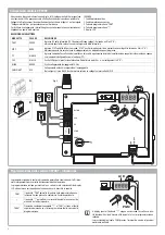
Collegamenti centrale CP.PONY

Ad esclusione del cavo di alimentazione di rete, tutti i collegamenti elettrici presentano
una tensione di 24V e possono essere effettuati anche da personale non qualificato.
Collegare tutti gli accessori facendo riferimento allo schema di figura 1 e al paragrafo 
"Collegamenti elettrici" per quanto concerne i tipi di cavo.
Per facilitare il collegamento i morsetti degli accessori presentano un colorazione cor-
rispondente a quella della centrale.

Fig.1

LEGENDA:
1 Fusibile protezione linea
2 Fusibile protezione accessori 
3 Pulsante programmazione "PGM"
4 Pulsante programmazione "

"

5 Display LCD

A

B

DESCRIZIONE MORSETTIERE

MORSETTO

COLORE

DESCRIZIONE

PHOT

VERDE

Ingresso NC dalla fotocellula RX. I due morsetti sono collegati tra loro da un filo (rif "A"). 
Rimuovere questo filo solo nel caso di collegamento della fotocellula.

STOP

NERO

Ingresso STOP contatto NC per comando "STOP" ausiliario (opzionale). I due morsetti sono collegati tra loro da un filo (rif "A"). 
Rimuovere questo filo solo nel caso di collegamento di un dispositivo a questo ingresso.

PP

BIANCO

Ingresso comando Passo-Passo dal selettore a chiave. Ad ogni impulso inviato dal selettore viene eseguita ciclicamente una sequen-
za di comandi configurabile con la funzione (PP).

24V

GIALLO

Uscita 24Vdc per alimentazione fotocellule. Rispettare le polarità + e- nei collegamenti (rif "B").

BLINK

ROSSO

Uscita collegamento lampeggiante 24 Vdc 

SHIELD/ANT

BLU

Collegamento antenna incorporata nel lampeggiante.
Nel collegare il cavo RG58, la schermatura esterna va collegata al morsetto SHIELD.

1

2

3

4

5

PHOT

STOP

PP

RX

TX

24V

-

+

BLINK

SHHIELD

ANT

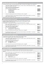
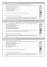
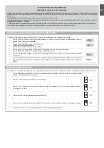
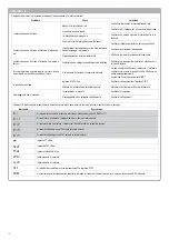
La programmazione della centrale di comando permette la regolazione di tutti i para-
metri indispensabili per il corretto funzionamento dell'automazione.
La programmazione avviene per mezzo di una serie di menù selezionabili da display 
LCD, ad ogni menù corrisponde una funzione che verrà descritta in seguito. 

PGM

Il pulsante "PGM" permette di entrare nella programmazione, se-
lezionare il menù prescelto, confermare il valore selezionato.

Il pulsante "

" permette di scorrere ciclicamente le varie voci del

menù ed i valori da impostare.

PGM+

Premendo contemporaneamente "

" e "PGM" si torna al livello

superiore del menù o se ci si trova già al primo livello, si esce dalla 
programmazione.

Programmazione della centrale CP.PONY - Introduzione

LCD

PGM

A  display  spento  il  pulsante  "

"  esegue  un  comando  Passo-Passo,  que-

sta  funzionalità  si  può  rilevare  utile  durante  le  fasi  di  programmazione  e 
collaudo.
La  pressione  del  pulsante  PGM,  provoca  l'immediato  arresto  di  qualsiasi 
movimento dell'anta.

Содержание 9592170

Страница 1: ...L8543230 06 2016 rev 0 PONY PONY 115 UNIONE NAZIONALE COSTRUTTORI AUTOMATISMI PER CANCELLI PORTE SERRANDE ED AFFINI IT EN DE FR ES PL...

Страница 2: ......

Страница 3: ...nstallazione la logica di funzionamento del sistema e le forze sviluppate dall automazione L installazione deve essere fatta utilizzando dispositivi di sicurezza e di comandi conformi alla EN12978 e E...

Страница 4: ...omodit 295 270 215 Dati Tecnici dimensioni e limiti di impiego DATI TECNICI PONY Alimentazione centrale di comando 230 Vac PONY 115 Vac PONY 115 50 60 Hz Alimentazione motore 24Vdc Potenza assorbita 8...

Страница 5: ...necessario realizzare una gabbia metallica per rendere pi stabile la fondazione 6 Annegare le barre nel cemento prestando attenzione al livello della piastra ed al parallelismo con l anta gura 8 7 At...

Страница 6: ...Fissaggio del motoriduttore Per il ssaggio del motoriduttore alla piastra con riferimento alla gura 13 procedere come segue 1 Rimuovere i due carter copriviti C 2 Posare il motoriduttore sulla piastra...

Страница 7: ...In fase di collaudo veri cate con alcune manovre di apertura e chiusura ura che il necorsa intervenga nei punti di apertura e chiusura corretti prima co co c delle rispettive battute meccaniche batt...

Страница 8: ...camente una sequen za di comandi con gurabile con la funzione PP 24V GIALLO Uscita 24Vdc per alimentazione fotocellule Rispettare le polarit e nei collegamenti rif B BLINK ROSSO Uscita collegamento la...

Страница 9: ...sovrascrive la precedente Effettuare una procedura di autoset dopo ogni intervento di manutenzione o modi ca della porta Regolazione del tempo di chiusura automatica TCA La funzione di chiusura autom...

Страница 10: ...rnativa togliere alimentazione o attendere 60 secondi PGM Regolazione del tempo di rallentamento TSM Se si desidera che l anta rallenti per alcuni secondi prima dell intervento dei necorsa selezionare...

Страница 11: ...anti PGM e o in alternativa togliere alimentazione o attendere 60 secondi PGM Funzione risparmio energetico ESA Se la funzione ESA attiva la centrale una volta terminata la manovra di apertura o chius...

Страница 12: ...menu PP Premere per visualizzare il sottomenu Ped Ped 3 Premere il pulsante PGM per entrare nella funzione Ped Il display visualizza il messaggio PUSH lampeggiante Push 4 Premere entro 10s il pulsante...

Страница 13: ...l pulsante PGM per entrare nella funzione RTR il messaggio RTR inizia a lampeggiare lentamente Premere PGM viene visualizzato il messaggio PRG ed ha inizio la cancellazione 4 Quando il messaggio PRG s...

Страница 14: ...li sbloccare il motore e verificare la presenza di punti di attrito Effettuare un nuovo autoapprendimento Aumentare il valore del parametro PMOT La porta non si chiude Ingresso STOP attivo Ostacolo tr...

Страница 15: ...ing logic of the system and forces generated by the automated system Installation must be carried out using safety devices and controls that meet stan dards EN 12978 and EN 12453 Only use original acc...

Страница 16: ...bsorbed power 80 W Absorption 0 6 A Torque 9 Nm Operative intermittence 30 Opening speed 10 m 1 Protection rating IP44 Functioning temperature 20 C 50 C Driving gear for rack M4 Z14 Noise 70 dB Weight...

Страница 17: ...t paying attention to the level of the plate and the parallelism with the leaf figure 8 7 Wait for the cement cast to be reinforced 8 Remove the upper screws and washers which will be successively use...

Страница 18: ...Fig 10 25 mm Max 20 mm Fig 11 Fig 12 Fixing the gear motor To x the motor reducer to the plate with reference to g 13 proceed as follows 1 Remove the two screw cover sumps C 2 Place the gear motor on...

Страница 19: ...opening and closing manoeuvres to ma ma ma check whether the end run intervenes in the correct opening and closing r the ng points before the respective mechanical profiles the If necessary move the...

Страница 20: ...ing the PP function is performed cyclically 24V YELLOW 24Vdc output for photocells power supply Respect the polarities and in the connections ref B BLINK RED 24Vdc ashing light connection output SHIEL...

Страница 21: ...autoset phase displaying the message ERR1 2 3 The procedure must therefore be repeated Every self regulation procedure overwrites the previous one Perform an autostop procedure after every maintenance...

Страница 22: ...and buttons at the same time or alternatively remove the power supply or wait 60 seconds PGM Regulation of the slowing time TSM If the leaf is to slow for a few seconds before the end run interventio...

Страница 23: ...and buttons at the same time or alternatively remove the power supply or wait 60 seconds PGM Energy saving functioning mode ESA With the ESA energy saving function activated when a full opening or clo...

Страница 24: ...PP Press to display the Ped sub menu Ped 3 Press the PGM button to enter the Ped function The display shows the flashing PUSH message Push 4 Press the BY transmitter button that is to be associated to...

Страница 25: ...sub menu PP Press three times to display the RTR sub menu rtr 3 Press the PGM button to enter the RTR function the RTR message starts to ash slowly Press PGM the PRG message is displayed and deleting...

Страница 26: ...he value of the PMOT parameter The door does not close STOP input active Obstacle between the photocells or photocells broken Check the connections of the STOP input Remove the obstacle or check the p...

Страница 27: ...umgebung die Betriebsweise sowie die vom System entwickelten Kr fte Die Installation muss unter Verwedung von Sicherheits und Steuerungsvorrichtungen vorgenommen werden die der Norm EN 12978 und EN 12...

Страница 28: ...ors 24Vdc Leistungsaufnahme 80 W Stromaufnahme 0 6 A Drehmoment 9 Nm Einschalth u gkeit 30 ffnungsgeschwindigkeit 10 m 1 Schutzart IP44 Betriebstemperatur 20 C 50 C Zahntriebritzel M4 Z14 Schallpegel...

Страница 29: ...hen 6 Versenken Sie die Stangen im Beton achten Sie dabei darauf dass die Ankerplatte waagerecht und parallel zum Tor sein muss Abbildung 8 7 Warten Sie die Aush rtung des Betons ab 8 Entfernen Sie di...

Страница 30: ...ors Gehen Sie zur Befestigung des Getriebemotors an der Ankerplatte wie folgt vor siehe auch Abb 13 1 Entfernen Sie die beiden Schraubenabdeckungen C 2 Setzen Sie den Getriebemotor so auf die Ankerpla...

Страница 31: ...r g ngen ob der Endschalter beim ffnen und Schlie en an den richtigen n d d Stellen d h vor den entsprechenden mechanischen Anschl gen ausl st de ge Gegebenenfalls m ssen Sie die Endanschl ge FRD 1 v...

Страница 32: ...unktion PP kon gurierbare Befehlsfolge ausgef hrt 24V GELB 24Vdc Ausgang f r die Stromversorgung der Lichtschranken Beachten Sie die Polarit t und bei den Anschl ssen siehe B BLINK ROT Ausgang Blinkan...

Страница 33: ...zeigt Somit muss die Prozedur widerholt werden Jede Selbstregelungsprozedur berschreibt die vorherige F hren Sie nach Wartungsarbeiten oder nderungen am Tor stets eine Autoset Prozedur durch Zeiteinst...

Страница 34: ...unterbrechen Sie die Stromversorgung oder warten Sie 60 Sekunden PGM Einstellung der Verlangsamungszeit TSM Wenn das Tor einige Sekunden vor Ausl sung des Endschalters verlangsamt werden soll w hlen...

Страница 35: ...er unterbrechen Sie die Stromversorgung oder warten Sie 60 Sekunden PGM Funktion Energieersparnis ESA Aktiviert oder deaktiviert die Funktion Energieersparnis ESA Nach dem ffnungs oder Schlie vorgang...

Страница 36: ...e um das Untermen Ped anzuzeigen Ped 3 Dr cken Sie die Taste PGM um die Funktion Ped aufzurufen Auf dem Display erscheint die blinkende Meldung PUSH Push 4 Dr cken Sie innerhalb 10 s die Taste von Sen...

Страница 37: ...nktion aufzurufen Im Display erscheint das erste Untermen PP Dr cken Sie zweimal um das Untermen RTR anzuzeigen rtr 3 Dr cken Sie die Taste PGM um die Funktion RTR aufzurufen die Meldung RTR beginnt l...

Страница 38: ...f hren Wert des Parameters PMOT erh hen Das Tor schlie t sich nicht Eingang STOP aktiv Hindernis zwischen den Lichtschranken oder Licht schranke defekt Anschl sse des Eingangs STOP berpr fen Hindernis...

Страница 39: ...la logique de functionnement du syst me et des forces d velopp es par l automatisation L installation doit tre quip e de dispositifs de s curit et de commandes conformes aux normes EN 12978 et EN 1245...

Страница 40: ...c PONY 115 50 60 Hz Alimentation du moteur 24Vdc Puissance absorb e 80 W Absorption 0 6 A Couple 9 Nm Intermittence de travail 30 Vitesse d ouverture 10 m 1 Degr de protection IP44 Temp rature de fonc...

Страница 41: ...yer les barres dans le ciment en tenant compte du niveau de la plaque et du parall lisme avec le portail Figure 8 7 Attendre la consolidation de la coul e de ciment 8 Enlever les vis et les rondelles...

Страница 42: ...tail A B 25 mm Fig 10 25 mm Max 20 mm Fig 11 Fig 12 Fixation du motor ducteur Pour la fixation du motor ducteur la plaque conform ment la Figure 13 proc der de la fa on suivante 1 Enlever les deux car...

Страница 43: ...fin de course intervient bien aux endroits d ouverture et de fermeture corrects avant les respectives but es m caniques Eventuellement d placer les triers FRD 1 pour anticiper ou pour retarder les po...

Страница 44: ...ectu e cycliquement 24V JAUNE Sortie 24Vdc pour alimentation des photocellules Pour les branchements r f B respecter la polarit et BLINK ROUGE Sortie branchement clignotant 24 Vdc SHIELD ANT BLEU Bran...

Страница 45: ...ERR1 2 3 Il faut par cons quent r p ter la proc dure Chaque proc dure de r glage automatique efface la pr c dente Il faut effectuer une proc dure de r glage automatique apr s chaque intervention de ma...

Страница 46: ...alimentation ou attendre 60 secondes PGM R glage du temps de ralentissement TSM Si on souhaite que le portail ralentisse pendant quelques secondes avant l intervention du fin de course s lectionner un...

Страница 47: ...tan ment sur les touches PGM e ou en alternative d brancher l alimentation ou attendre 60 secondes PGM Fonction d conomie d nergie ESA Si la fonction ESA est active une fois la man uvre d ouverture ou...

Страница 48: ...u PP Appuyer sur pour visualiser le sous menu Ped Ped 3 Appuyer sur le bouton PGM pour acc der la fonction Ped L af cheur visualise le message PUSH qui clignote Push 4 Appuyer dans les 10 secondes qui...

Страница 49: ...premier sous menu PP Appuyer trois fois sur pour visualiser le sous menu RTR rtr 3 Appuyer sur la touche PGM pour entrer dans la fonction RTR le message RTR commence clignoter lentement Appuyer sur PG...

Страница 50: ...sent d bloquer le moteur et v ri er qu il n y ait pas de points de frottement Ef fectuer un nouvel auto apprentissage Augmenter la valeur du param tre PMOT La porte ne se ferme pas Entr e STOP activ e...

Страница 51: ...s fuerzas desarrolladas por la automatizaci n La instalaci n se debe realizar utilizando dispositivos de seguridad y de mandos conformes a la EN 12978 y EN12453 Usar exclusivamente accesorios y repues...

Страница 52: ...6 A PONY 1 2 A PONY 115 Par 9 Nm Intermitencia de trabajo 15 ciclos hora 80 ciclos d a Velocidad de apertura 10 m 1 Grado de protecci n IP44 Temperatura de funcionamiento 20 C 70 C Pi n para cremalle...

Страница 53: ...cimentaci n 6 Embeber las barras en el cemento prestando atenci n al nivel de la placa y al paralelismo con la hoja gura 8 7 Espere a que se solidi que la colada de cemento 8 Quite los tornillos y la...

Страница 54: ...Fijaci n del motorreductor Para jar el motorreductor a la placa consulte la gura 13 y act e de la siguiente manera 1 Quite los dos c rteres que cubren los tornillos C 2 Coloque el motorreductor en la...

Страница 55: ...rtura y cierre que el nal de carrera intervenga en los puntos de apertura y cierre co ra a rrectos antes de los respectivos topes mec nicos e lo De ser necesario desplace las abrazaderas FRD 1 para an...

Страница 56: ...puede con gurar con la funci n PP 24V AMARILLO Salida de 24 Vdc para alimentaci n de fotoc lulas Respete las polaridades y en las conexiones ref B BLINK ROJO Salida de la conexi n de la l mpara destel...

Страница 57: ...r el procedimiento Cada procedimiento de autorregulaci n sobrescribe el precedente Realice un proceso de autorregulaci n despu s de cada intervenci n de mantenimiento o modi caci n de la puerta Regula...

Страница 58: ...o alternativamente quite la alimentaci n o espere 60 segundos PGM Regulaci n del tiempo de ralentizaci n TSM Si se desea que la hoja ralentice durante algunos segundos antes de que intervengan los na...

Страница 59: ...e la programaci n presione simult neamente los pulsadores PGM y o alternativamen te quite la alimentaci n o espere 60 segundos PGM Funci n de ahorro de energ a ESA Si la funci n ESA est activada la un...

Страница 60: ...iza el primer submen PP Presione para visualizar el submen Ped Ped 3 Presione el pulsador PGM para entrar en la funci n Ped La pantalla visualiza el mensaje PUSH intermitente Push 4 Presione dentro de...

Страница 61: ...bmen RTR rtr 3 Presione el pulsador PGM para entrar en la funci n RTR el mensaje RTR comienza a parpadear lentamente Presione PGM se visualiza el mensaje PRG y se comienza a borrar 4 Cuando se apaga e...

Страница 62: ...sbloquee el motor y controle la presencia de puntos de roce Realice un nuevo au toaprendizaje Aumente el valor del par metro PMOT La puerta no se cierra Entrada STOP activa Obst culo entre las fotoc l...

Страница 63: ...techniczne spos b eksploatacji otoczenie monta owe zasad dzia ania urz dzenia oraz si y wytwarzane przez automatyke Podczas instalacji nale y wykorzysta zabezpieczenia i sterowniki spe niaj ce wymogi...

Страница 64: ...wy 50 min 30 Pr dko otwierania 10 m min 10 m 1 Klasa ochrony IP44 IP44 Temperatura pracy 20 C 60 C 20 C 50 C Modu ko a zewn trznego M4 Z14 M4 Z14 Ha as 70 dB 70 dB Ci ar 6 8 kg 6 8 kg WYMIARY Na Rys 1...

Страница 65: ...poziom p yty i zachowanie r wnoleg o ci w stosunku do skrzyd a bramy Rys 8 7 Odczeka a beton stwardnieje 8 Odkr ci g rne nakr tki i zdj podk adki kt re zostan wykorzystane do zamo cowania motoreduktor...

Страница 66: ...d a bramy A B 25 mm Fig 10 25 mm Max 20 mm Fig 11 Fig 12 Mocowanie motoreduktora Motoreduktor nale y przymocowa do p yty w spos b przedstawiony na Rys 13 1 Wykr ci dwie ruby znajduj ce si pod os on C...

Страница 67: ...nie otworzy i zamkn bram w celu sprawdzania czy aw wy cznik kra cowy zadzia a we w a ciwym po o eniu skrzyd a bramy krz krz kr zanim zetknie si ono z odpowiednimi ogranicznikami mechanicznymi si o W r...

Страница 68: ...nym z tego prze cznika wykonywana jest cyklicznie sekwencja polece kt re mo na skon gurowa za pomoc funkcji PP 24V TY 24 V DC wyj cie do zasilania fotokom rek Odpowiednio do polaryzacji i ref B BLINK...

Страница 69: ...autotestu i wy wietla komunikat o b dzie ERR1 2 3 Procedura musi by powt rzona Ka da procedura automatycznej regulacji zast puje wynik poprzedniej Po ka dej konserwacji lub mody kacji drzwi nale y pow...

Страница 70: ...lub wy cz zasilanie wzgl odczekaj 60 sekund PGM Regulacja fazy spowalniania TSM Je li ruch drzwi jest zbyt powolny na kilka sekund przed ko cem wybierz jedn z dost pnych warto ci jak opisano poni ej...

Страница 71: ...ca przejdzie ponownie do menu MINV Aby wyj z trybu programowania naci nij r wnocze nie przyciski PGM i lub wy cz zasilanie wzgl odczekaj 60 sekund PGM Tryb oszcz dzania energii ESA W trybie oszcz dza...

Страница 72: ...ij przycisk aby wy wietli podmenu Ped Ped 3 Naci nij przycisk PGM aby wej do funkcji Ped Na wy wietlaczu pojawi si migaj cy komunikat PUSH Push 4 W ci gu 10 sekund naci nij na nadajniku przycisk BY kt...

Страница 73: ...j przycisk PGM aby wej do funkcji RTR komunikat RTR zacznie miga powoli Naci nij przycisk PGM na wy wietlaczu pojawi si komunikat PRG i rozpocznie si usuwanie 4 Gdy komunika PRG zniknie na wy wietlacz...

Страница 74: ...ametru PMOT Drzwi nie zamykaj si Wej cie STOP jest aktywne Przeszkoda pomi dzy fotokom rkami lub uszkodzone fotokom rki Sprawdzi po czenia wej cia STOP Usun przeszkod lub sprawdzi fotokom rki wiat o m...

Страница 75: ...turn Move the leaf manually to open and close the gate 4 To restore automatic functioning turn the key anti clockwise until it stops User guide MAINTENANCE Periodically check the ef ciency of the manu...

Страница 76: ...desbloqueo FRD 3 y g rela en sentido horario hasta advertir una cierta resistencia Se necesitan aproximadamente 15 rotaciones completas de la llave 3 Entonces el engranaje est desvinculado y libre pa...

Страница 77: ...0 N Code Note 1 9688164 2 9688165 3 9686414 4 9688166 5 9686622 PONY 9688142 PONY 115 6 9686623 7 9686624 8 9688169 9 9686626 10 9688170 PONY 9688143 PONY 115 11 9686488 12 9688174 Parti di ricambio S...

Страница 78: ...HVVR LO SURGXWWRUH O HUWLILFDWR GL RQIRUPLWj SL FRPSOHWR H UHFHQWH q GLVSRQLELOH FRQVXOWDQGR LO VLWR ZZZ EHQLQFD FRP RSSXUH SXz HVVHUH ULFKLHVWR SUHVVR XWRPDWLVPL HQLQFj 6 S 6DQGULJR 9 WDO 8 HFODUDWLR...

Страница 79: ...6S 6DQGULJR 9 7 pFODUDWLRQ GH FRQIRUPLWp R 1RP GX SURGXFWHXU XWRPDWLVPL HQLQFj 6S GUHVVH 9LD DSLWHOOR 6DQGULJR 9 WDOLD 7pOpSKRQH GUHVVH H PDLO VDOHV EHQLQFD LW 3HUVRQQH DXWRULVpH j FRQVWUXLUH OD GRFXP...

Страница 80: ...VHQWH HQ HVWH GRFXPHQWR FRUUHVSRQGH D OD OWLPD UHYLVLyQ GLVSRQLEOH HQ HO PRPHQWR GH OD LPSUHVLyQ SRGUtD GLIHULU SRU H LJHQFLDV HGLWRULDOHV GHO RULJLQDO GLVSRQLEOH HQ OD VHGH GHO IDEULFDQWH O FHUWLILFD...

Отзывы: