


Benezan Electronics
Hard- and software development
Triple Beast Installation Guide
Nicolas Benezan, Stauffenbergstr. 26, 72108 Rottenburg
Phone: +49 (0) 7457/946365 0 benezan-electronics.de
Page
TripleBeast-NET Installation.docx22.09.2020
The Triple BEAST must be connected either directly to the PC or to the first switch after the PC. A further switch may
only be added if only devices of the machine are connected to the second switch, e.g. within the control cabinet of the
machine. All devices not involved in machine control (Internet router, printer, NAS, etc.) must be connected to the first
switch or to additional switches behind the first.
The transmission speed between the PC and the first switch must be higher than the maximum data rate of any existing
Internet routers (DSL modem etc.). For home networks with few PCs 100MBit is recommended, for larger networks
Gigabit-Ethernet.
Since no TCP/IP is used but a separate protocol, this cannot be forwarded by routers, external firewalls, proxies, etc.
Therefore only so-called "unmanaged switches" may be used between the control PC and the CNC pod.
Switches must support Fast Forward and Store-and-Forward (virtually all modern switches meet this criterion)
Hubs are also allowed for test purposes (listening with diagnostic tools on taps), but are not recommended.
The data traffic of the machine controller must not be routed via slow (DSL modem) or unreliable (wireless) connections
(WLAN). All wireless interfaces are therefore intentionally hidden.
If the Triple BEAST is connected directly to the PC and the PC interface does not support automatic crossover, a crossover
cable must be used (usually marked with a red plug or "X"). The network interface is galvanically isolated from the PC. Power-
over-Ethernet (PoE) is not supported.
Reference switch inputs
Up to 4 switches or inductive sensors can be connected. If the 4th axis is not used or does not require a reference switch, a tool
length sensor can also be connected here, for example.
Mechanical switches or inductive proximity switches of the PNP type can be used. With the jumpers 12-13 or 13-14 the supply
voltage for the switches can be selected (see picture on page 6).
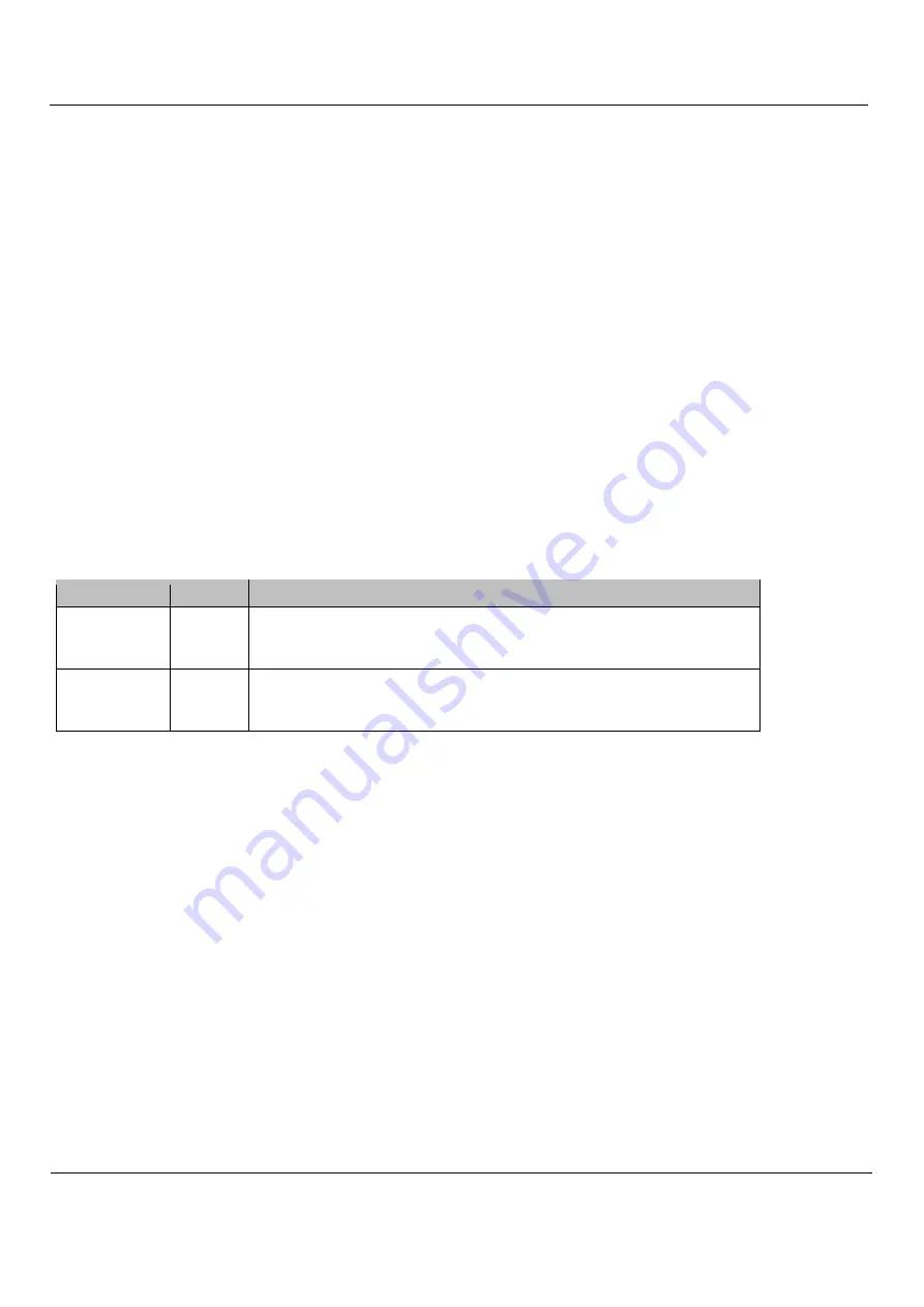
Jumper setting Voltage
Description
▪ ▪ ▬ ▪ 13-14
12V
(internal
regulator)
recommended for mechanical switches
also for inductive switches, if they are specified for 12V
Input voltage at X1.5 any (15..55V)
▪ ▪ ▪ ▬ 12-13
24V
(connected
with X1.5)
recommended for inductive switches (industry standard)
also possible for mechanical switches (mixed types)
separate 24V power supply unit required at X1 if motor voltage >24V
Inductive proximity switches or other sensors should be connected as follows: brown (+24V) to terminal 1, 3, 5 or 7, blue to
the ground connection of the power supply, black (signal) to terminal 2, 4, 6 or 8.
The inputs are high-active, i.e. the signal is logic 1 when the connected switch is closed, or when a voltage >8V is present at the
input. The signal is logic 0 when the input is de-energized or the switch is open. If required, all input signals can be inverted in the
software.
The switch inputs have a Schmitt trigger function and are interference suppressed with a low-pass filter, so that there is usually
no need to fear interference even with unshielded cables. The inputs are overvoltage tolerant up to +80V. Please note that the
switch inputs are not suitable for fast signals (>1kHz) with 5V level, for example TTL encoder signals.
If more than four inputs are required for additional functions, an additional IO expansion module can be installed.


