background image

Benezan Electronics


Hard- and software development


Triple Beast Installation Guide


Nicolas Benezan, Stauffenbergstr. 26, 72108 Rottenburg 
Phone: +49 (0) 7457/946365 0 benezan-electronics.de 

Page 

TripleBeast-NET Installation.docx22.09.2020 


Status LEDs 

The status displays of the power amplifiers are located on the left side (see picture below). The different colours or combinations 
thereof indicate the following operating states: 

LEDs 

Lettering 

Description 

(green) 

Running 

Motor(s) running, no current reduction 

(yellow) 

Standby 

Motors stand still, current reduction 

(red blinking) 

Fault Axis...  A  single  red  flashing  LED  indicates  a  short  circuit,  overload  or  faulty 

wiring  on  the  corresponding  motor. The  other  motors  and  the  yellow  or 
green LED remain active. 

(red blinking) 

Fault Axis...  If  all  red  LEDs  flash  simultaneously  when  the  green  and  yellow  LEDs 

are switched off, the output stage is overheated. All motors are switched 
off. 

(yellow/red 
alternating) 

Fault Axis...  If the yellow and all red LEDs flash alternately, the power stage has been 

deactivated due to overvoltage. The cause can be braking energy from the 
motors or an incorrectly dimensioned power supply unit. 


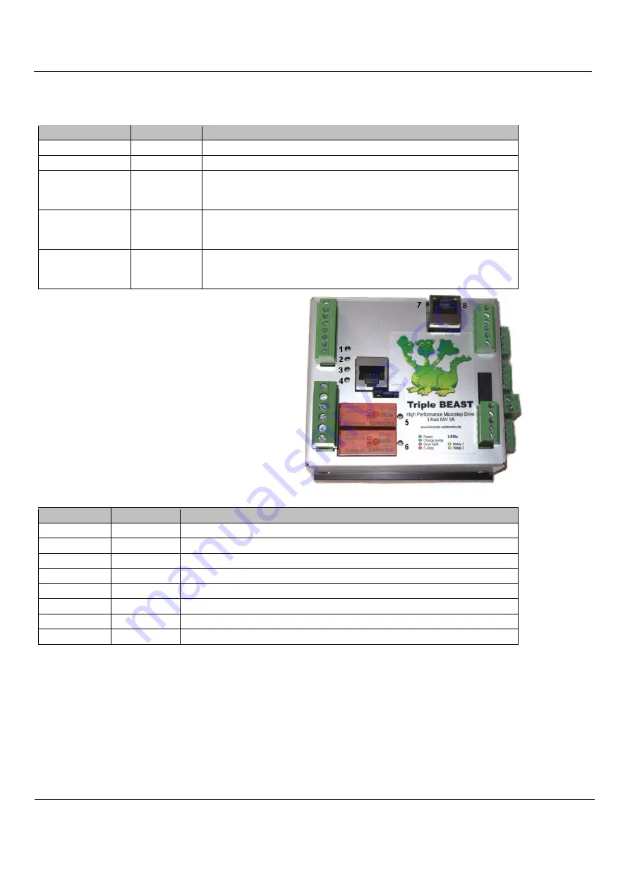
On  the  left  below  the  middle  of  the  housing,  between 

the  RJ45  socket  for  the  4th  axis  and  the  relays,  there  is  a 
pin  header  with  five  contacts  and  two  jumpers.  These  are 
numbered  from  right  to  left  with  no.  12  to  16  and  are 
described further below. 


The LEDs on the upper side indicate the status of the PC interface. 

LEDs 

Lettering 

Description 

1 (green) 

Power 

Power supply ok 

2 (green) 

Batch pump  Watchdog (charge pump) active 

3 (red) 

Drive fault 

One or more output stages report an error 

4 (red) 

E-Stop 

Emergency stop switch activated or line interrupted 

5 (yellow) 

Relay 1 

Relay 1 switched on (spindle motor) 

6 (yellow) 

Relay 2 

Relay 2 switched on (coolant or suction) 

7 (green) 

Network connection established (Network carrier) 

8 (yellow) 

Network data transmission (network traffic) 

PC / network connection 

The  data  transfer  from  the  PC  software  to  the  Triple  BEAST  takes  place  via  an  Ethernet  network  connection  (IEEE802.3 
10BASE-T).  The  connection  can  be  made  with  standard  patch  cables  at  the  RJ45  socket  "N".  Please  note  that  the  other  RJ45 
socket "A4" (without  LEDs,  see figure page 4) is not a network connection, but is intended for the step/direction signals of the 
external 4th axis. 

In contrast to similar products from competitors (e.g. Smoothstepper or Eding-CNC) no exclusive interface has to be reserved 

on the PC, but the infrastructure of an existing network with switches can be used. There is also no need to change IP addresses or 
otherwise interfere with the Windows Control Panel. The Beamicon2 software automatically recognizes the Triple BEAST, even 
if it is connected "somewhere" in the network. To ensure reliable operation, however, the following rules must be observed: 

Содержание TripleBeast

Страница 1: ...still required The effort for mounting wiring and the possibilities for errors are thus reduced to a minimum The Triple BEAST offers all the advantages of the individual BEAST power amplifier at extre...

Страница 2: ...lutely necessary More detailed selection criteria are listed in the chapter0 3 A PC with Beamicon2 CNC software and a RJ45 network cable patch cable Please note that this version of the Triple BEAST i...

Страница 3: ...Signal input 7 Reference switch 4th axis voltage output 12 24V 8 Reference switch 4th axis Signal input Relay outputs 6 pin terminal X4 bottom left No Description 1 230V L Input 2 230V N Input 3 Relay...

Страница 4: ...d power supply consisting of transformer rectifier and filter capacitor is also suitable Please note however that the voltage range must be maintained even with mains and load fluctuations usually 10...

Страница 5: ...for all axes simultaneously Simultaneous operation of very small and very large motors is therefore not possible Depending on the selected range the fine adjustment can then be carried out separately...

Страница 6: ...jumpers These are numbered from right to left with no 12 to 16 and are described further below The LEDs on the upper side indicate the status of the PC interface LEDs Lettering Description 1 green Pow...

Страница 7: ...a red plug or X The network interface is galvanically isolated from the PC Power over Ethernet PoE is not supported Reference switch inputs Up to 4 switches or inductive sensors can be connected If th...

Страница 8: ...upply ground However this is not a problem with all modern frequency inverters because they have an isolated speed input Care should be taken with old thyristor controllers whose speed input is partia...

Страница 9: ...nected to the supply voltage of the power supply X1 5 This is useful if a 24V power supply unit is connected there and the switches used are inductive proximity switches or similar industrial sensors...

Страница 10: ...neously as a reference and limit switch The following output signals are available and can be assigned to the logical signals in the software right table Pin Name Signal Description Release Current re...

Страница 11: ...purposes only a jumper may be connected between pins 5 and 6 of X2 as an alternative An emergency stop switch is legally required on a machine If these requirements are met you can establish the conne...

Страница 12: ...selected if several modules are in the network 4 LED Charge Pump green is not lit a ChargePump signal not assigned or module is not connected b Software not started or running in demo mode 5 LED Drive...

Страница 13: ...age at the relay terminals 30 Vdc 250 Vac Current per relay contact X4 8 Aeff Current at brake relay X2 5 A Current at analog output 0 10V 20 mA Electrical connection values Parameters min max Unit Op...

Отзывы: