Benezan Electronics TripleBeast Скачать руководство пользователя страница 10

Benezan Electronics


Hard- and software development


Triple Beast Installation Guide


Nicolas Benezan, Stauffenbergstr. 26, 72108 Rottenburg 
Phone: +49 (0) 7457/946365 0 benezan-electronics.de 

Page 

TripleBeast-NET Installation.docx22.09.2020 


The step and direction signals for a maximum of 4 axes are automatically assigned to the three motors and the RJ45 socket. No 

settings need to be made for this. In particular, there is no need to set a pulse time, as the step signal always has a 50% duty cycle. 
The  direction  of  movement  can  be  reversed  in  the  machine  parameters  (Menu  ->  Configuration  ->  Machine)  on  the  "Axis 
Parameters" page with the "Inverted direction" button. 

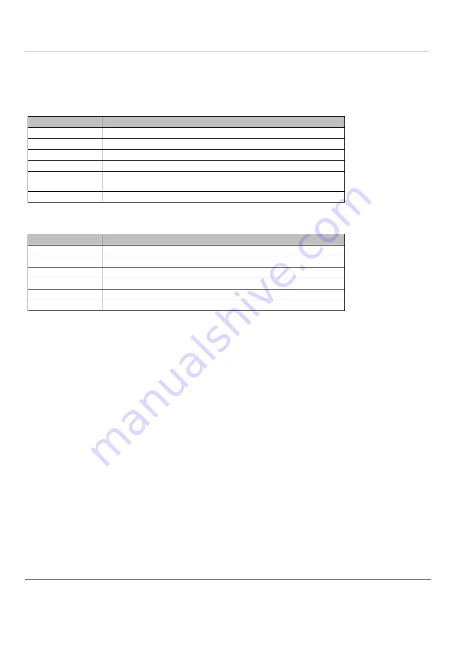
For  the  assignment  of  the  signals  switch  to  the  page  "Inputs/Outputs".  The  following  input  signals  are  available  and  can  be 

assigned to the logical signals (left table in the software): 

Pin Name 

Signal Description 

Input 1 

Switch input no. 1 (terminal X3.2) 

Input 2 

Switch input no. 2 (terminal X3.4) 

Input 3 

Switch input no. 3 (terminal X3.6) 

Input 4 

Switch input no. 4 (terminal X3.8) 

Emergency stop 

Emergency stop (triggered by mushroom button terminal X2.6, undervoltage 
or connection error) 

D error 

Drive error, one of the stepper motor or servo output stages reports error 

Input  signals  can  be  used  multiple  times  if  required.  For  example,  the  same  switch  input  can  be  used  simultaneously  as  a 

reference and limit switch. 

The following output signals are available and can be assigned to the logical signals (in the software right table): 

Pin Name 

Signal Description 

Release 

Current reduction signal or servo enable to the output stages 

Relay 1 

Relay no. 1, contacts X4.3 and X4.4 

Relay 2 

Relay no. 2, contacts X4.5 and X4.6 

Brake 

Relay for holding brake or frequency converter start, terminal X2.2 

PWM 

PWM signal for analog output, terminal X2.4 

WDog 

Watchdog/Charge-Pump-Signal, switches all outputs free 

Unlike inputs, output signals cannot be inverted (active low/hi) because otherwise the safe off state would not be defined. For 

the function of all other outputs the charge pump signal must be assigned to pin "WDog". Otherwise all outputs, including the step 
signals, are disabled. 

When using stepper motor output stages, the current reduction signal must be applied to the enable pin. This is always active 

when  all  drives  are  stopped.  When  using  servos,  however,  the  servo  enable  signal  must  be  assigned  to  the  enable  pin.  This  is 
active when the drives are moving. 

The relays can be assigned to any other output signals. Examples: 


Standard assignment: Relay 1 = spindle forward, relay 2 = coolant, brake = holding brake 


no brake, FU, add. spray cooling: relay1 = coolant, relay2 = spray cooling, brake = spindle forward 


Spindle with right/left rotation: relay1 = spindle forward, relay2 = spindle reverse 

If  the  number  of  available  outputs  or  inputs  is  not  sufficient  for  the  application,  they  can  be  increased  with  an  expansion 

module. 


Содержание TripleBeast

Страница 1: ...still required The effort for mounting wiring and the possibilities for errors are thus reduced to a minimum The Triple BEAST offers all the advantages of the individual BEAST power amplifier at extre...

Страница 2: ...lutely necessary More detailed selection criteria are listed in the chapter0 3 A PC with Beamicon2 CNC software and a RJ45 network cable patch cable Please note that this version of the Triple BEAST i...

Страница 3: ...Signal input 7 Reference switch 4th axis voltage output 12 24V 8 Reference switch 4th axis Signal input Relay outputs 6 pin terminal X4 bottom left No Description 1 230V L Input 2 230V N Input 3 Relay...

Страница 4: ...d power supply consisting of transformer rectifier and filter capacitor is also suitable Please note however that the voltage range must be maintained even with mains and load fluctuations usually 10...

Страница 5: ...for all axes simultaneously Simultaneous operation of very small and very large motors is therefore not possible Depending on the selected range the fine adjustment can then be carried out separately...

Страница 6: ...jumpers These are numbered from right to left with no 12 to 16 and are described further below The LEDs on the upper side indicate the status of the PC interface LEDs Lettering Description 1 green Pow...

Страница 7: ...a red plug or X The network interface is galvanically isolated from the PC Power over Ethernet PoE is not supported Reference switch inputs Up to 4 switches or inductive sensors can be connected If th...

Страница 8: ...upply ground However this is not a problem with all modern frequency inverters because they have an isolated speed input Care should be taken with old thyristor controllers whose speed input is partia...

Страница 9: ...nected to the supply voltage of the power supply X1 5 This is useful if a 24V power supply unit is connected there and the switches used are inductive proximity switches or similar industrial sensors...

Страница 10: ...neously as a reference and limit switch The following output signals are available and can be assigned to the logical signals in the software right table Pin Name Signal Description Release Current re...

Страница 11: ...purposes only a jumper may be connected between pins 5 and 6 of X2 as an alternative An emergency stop switch is legally required on a machine If these requirements are met you can establish the conne...

Страница 12: ...selected if several modules are in the network 4 LED Charge Pump green is not lit a ChargePump signal not assigned or module is not connected b Software not started or running in demo mode 5 LED Drive...

Страница 13: ...age at the relay terminals 30 Vdc 250 Vac Current per relay contact X4 8 Aeff Current at brake relay X2 5 A Current at analog output 0 10V 20 mA Electrical connection values Parameters min max Unit Op...

Отзывы: