Bender EDS3090 Скачать руководство пользователя страница 59

Technical specifications

59

EDS309x_D00012_03_M_XXEN/11.2014

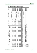
7.9   Ordering data including accessories

Type

Supply voltage

Nominal voltage

Art.-No.

Insulation fault 

locator

Locating current 

injector

Measuring

clamps 20 mm

Measuring

clamps

 52 mm

EDS3090

EDS195P

PSA3020

PSA3052

B91082026

EDS3090PG

EDS195P

PGH185

PSA3020

PSA3052

AC 50...60 Hz, 230 V

B91082021

EDS3090PG-13

EDS195P

PGH185-13

PSA3020

PSA3052

AC 50...60 Hz, 90…132 V

B91082022

EDS3091

EDS195P

PSA3320

PSA3352

B91082027

EDS3091PG

EDS195P

PGH183

PSA3320

PSA3352

AC 50...60 Hz, 230 V

B91082023

EDS3091PG-13

EDS195P

PGH183-13

PSA3320

PSA3352

AC 50...60 Hz, 90…132 V

B91082024

PGH183

PSA3320

PSA3352

AC 50...60 Hz, 230 V

AC 42...460 Hz, 20...265 V 

und DC 20...308 V

PGH185

PSA3020

PSA3052

AC 50...60 Hz, 230 V

AC 42...460 Hz, 20...575 V 

und DC 20...504 V

EDS3096PG

EDS195P

PGH186

PSA3020

PSA3052

AC 50...60 Hz, 230 V

B91082025

EDS3096PG-13

EDS195P

PGH186-13

PSA3020

PSA3052

AC 50...60 Hz, 90…132 V

B91082029

PSA3165

B980852

AGE185

AC 42...460 Hz, 500...790 V, 

DC 400...960 V

B980305

Adapter cable 

BNC-PS2

B91082045

EDS-SET

B91082007

Plug power 

supply with USB 

connector

A167054

DC 5 V for external supply of the EDS195P via µUSB connector

Measuring clamp 115 mm for EDS3090... and EDS3096...

AC 42...460 Hz, 20...575 V 

und DC 20...504 V

AC 42...460 Hz, 20...265 V 

und DC 20...308 V

EDS3092PG

AC 42...460 Hz, 0...575 V 

und DC 0...504 V

EDS195P

B91082030

Items supplied

Optional Accessories

BNC T-piece and 2 BNC cables for fault location in diode-decoupled systems

Coupling device for increasing the voltage range of the PGH185/186

Adapter cable for operating a WF current transformer on the EDS195P

Type

Supply voltage

Nominal voltage

Art.-No.

,QVXODWLRQIDXOW ORFDWRU

/RFDWLQJFXUUHQW LQMHFWRU

0HDVXULQJ

FODPSVPP

0HDVXULQJ

FODPSV

PP

('6

('63

36$

36$

%

('63*

('63

3*+

36$

36$

$&+]9

%

('63*

('63

3*+

36$

36$

$&+]«9

%

('6

('63

36$

36$

%

('63*

('63

3*+

36$

36$

$&+]9

%

('63*

('63

3*+

36$

36$

$&+]«9

%

3*+

36$

36$

$&+]9

$&+]9

XQG'&9

3*+

36$

36$

$&+]9

$&+]9

XQG'&9

('63*

('63

3*+

36$

36$

$&+]9

%

('63*

('63

3*+

36$

36$

$&+]«9

%

('639

('63

3*+

±

[36$

$&+]9

%

36$

%

$*(

$&+]9

'&9

%

$GDSWHUFDEOH %1&36

%

('66(7

%

3OXJSRZHU VXSSO\ZLWK86% FRQQHFWRU

$

%

Items supplied

Optional Accessories

%1&

7HHFRQQHFWRUDQG%1&FDEOHVIRUIDXOWORFDWLRQLQGLRGHGHFRXSOHGV\VWHPV

&RXSOLQJGHYLFHIRULQFUHDVLQJWKHYROWDJHUDQJH

$GDSWHUFDEOHIRURSHUDWLQJD:)FXUUHQWWUDQVIRUPHURQWKH('63

'&9IRUH[WHUQDOVXSSO\RIWKH('63YLD—86%FRQQHFWRU

0HDVXULQJFODPSPPIRU('6DQG('6

$&+]9

XQG'&9

$&+]9

XQG'&9

('63*

('63

$&+]9

XQG'&9

Содержание EDS3090

Страница 1: ...6 EDS195P ISOSCAN I s I n ALARM I n I s INFO MENU HOLD RESET ESC OK Portable equipment for insulation fault location for energised and deenergised AC and DC systems Software version D399 V2 0 EDS309x_...

Страница 2: ...Stra e 65 35305 Gr nberg Germany Tel 49 6401 807 0 Fax 49 6401 807 259 E mail info bender de www bender de Bender GmbH Co KG All rights reserved Reprinting only with permission of the publisher Subjec...

Страница 3: ...he system components 14 3 2 1 Locating current injector PGH18 14 3 2 2 Insulation fault locator EDS195P 14 3 2 3 Measuring clamps 14 3 2 4 Coupling device AGE185 15 3 3 Operating principle for insulat...

Страница 4: ...ontrols on the PGH18 32 6 5 Displays and controls on the EDS195P 33 6 6 Operating the EDS195P 34 6 6 1 Switching on and off the device 34 6 6 2 Changing the measuring clamp 35 6 6 3 Improved legibilit...

Страница 5: ...S195P as a residual current meter 49 6 12 5 Indication of the harmonics during residual current measurement 50 6 13 Coupling device AGE185 for higher system voltages 51 6 14 Power supply for the EDS19...

Страница 6: ...Table of Contents 6 EDS309x_D00012_03_M_XXEN 11 2014...

Страница 7: ...our Service Department for more information Service helpline 0700 BenderHelp telephone and fax Carl Benz Strasse 10 35305 Gruenberg Germany Tel 49 6401 807 760 Fax 49 6401 807 629 E mail info bender s...

Страница 8: ...al aspects of insulation fault location and provides numerous characteristic curves for assessing the response values to be set 5 Connecting the locating current injector The connection of the PGH18 t...

Страница 9: ...instructions System interference and high system leakage capacitances can degrade the ac curacy of the measurement Hazard due to excessively high locating current or excessively high locating voltage...

Страница 10: ...m part of the documentation for this device 2 4 Qualified personnel Only a qualified electrician is allowed to use the EDS3090 devices The electrician should be familiar with the assembly commissionin...

Страница 11: ...ircuits Clamp inside diameter 20 mm 3 Locating current injector PGH18 For generating a locating current for insulation fault location 4 Insulation fault locator EDS195P For connecting measuring clamps...

Страница 12: ...ating current generator PGH185 supplied AC 50 60 Hz 230 V EDS3090PG 13 Can be used in IT systems in which neither a locating current injector PGH471 nor an IRDH575 is already installed Supply voltage...

Страница 13: ...current injector PGH473 nor an IRDH575 is already installed Supply voltage for the locating current generator PGH183 13 supplied AC 50 60 Hz 90 132 V Equipment for insulation fault location in main ci...

Страница 14: ...tion fault location with IRDH575 or PGH1 as well as EDS46 49 Residual current measurement I n RCM mode for usage in TN or TT AC systems The response value range can be found in table 3 1 on page 14 Re...

Страница 15: ...ce The locating current produced as a result is dependent on the magnitude of the insulation fault present and the system voltage For example the locating current on the EDS3090 is limited to maximum...

Страница 16: ...ocating current pulses The sketch below shows the test cycle of the PGH with the different switch settings 1 2 3 on the device see schematic diagram above EDS195P Insulation fault locator PGH Locating...

Страница 17: ...The residual currents I n that flow through the system leakage capacitances CE V and CE N or that are caused by RF V and RF N Transient leakage currents that are caused by switching and control activ...

Страница 18: ...of the two currents is zero The EDS195P detects this situation there is no message Abb 3 2 Part of the current flows through an insulation fault RF The sum of the two currents is no longer zero As so...

Страница 19: ...d circuit in which a locating current IL dependent on the sys tem voltage flows The locating current is limited to a maximum value of 25 mA or 10 mA PGH185 186 2 5 mA or 1 mA PGH183 The locating curre...

Страница 20: ...PG EDS3090PG 13 EDS3092PG EDS3096PG 13 EDS3096PV EDS3096PG maximum 10 A Control circuits with EDS3091 EDS3091PG EDS3091PG 13 EDS3092PG maximum 1 A There must be no connections to other outgoing circui...

Страница 21: ...stream of the measuring current transform er will not be detected in certain circumstances Low frequency residual currents e g caused by converters can mean that insulation faults are not found if the...

Страница 22: ...P for usage in AC and 3AC systems as follows Tab 4 1 Settings for the EDS195P and the PGH18 For the response value setting see menu item 2 Settings 2 I L on page 39 The response values are given as ch...

Страница 23: ...cteristics shown indicate the response sensitivity of the EDS195P in main circuits for 2 mA 5 mA and 10 mA and in control circuits for 0 2 mA 0 5 mA and 1 mA Values above the related curve cannot be m...

Страница 24: ...200 250 300 R F k Ce uF AC 110V 2mA 5mA 10mA 0 10 20 30 40 50 60 0 50 100 150 R F k Ce uF AC 230V 2mA 5mA 10mA 0 10 20 30 40 50 60 70 80 90 100 0 20 40 60 80 100 R F k Ce uF AC 400V 2mA 5mA 10mA 0 2...

Страница 25: ...0 50 100 150 200 250 0 2 4 6 8 10 12 R F k Ce uF AC 110V 0 2mA 0 5mA 1mA 0 100 200 300 400 500 600 0 2 4 6 8 R F k Ce uF AC 230V 0 2mA 0 5mA 1mA 0 20 40 60 80 100 120 0 10 20 30 40 50 60 R F k Ce uF...

Страница 26: ...Considerations prior to use 26 EDS309x_D00012_03_M_XXEN 11 2014...

Страница 27: ...t location in electrically isolated systems using the EDS3096PG the integrated voltage source G in the PGH186 supplies a locating voltage The locating voltage DC 50 V is provided by the PGH186 at the...

Страница 28: ...s reason prevent any physical contact with active conductors and follow the rules for working on electrical systems Risk of electric shock If the PGH18 is connected using terminals L1 L2 L3 or L1 L2 t...

Страница 29: ...al contact with active conductors and follow the rules for working on electrical systems Risk of electric shock IfthePGH186isconnectedusingterminalsL1 undL2 toasystemthatislive due to its operation th...

Страница 30: ...cables of a string are ar ranged in a way that the measuring clamp PSA30 can be put around the cables Insulation faults in the strings can be localised by means of two measuring clamps connected in p...

Страница 31: ...t measuring clamp to PE conductor between PGH18 IRDH575 and for example PE rail to demonstrate that the necessary locating current IL is flowing 7 Place measuring clamp around the associated active co...

Страница 32: ...sing for fastening to metal items e g switch cabinet 4 3 sockets for coupling to system 5 Socket for PE connection 6 Indicator LEDs ON Operation LED Indication of positive locating current cycle Indic...

Страница 33: ...50 mA PSA33xx PSA33 suitable for ILmax 5 mA W WS 8000 W 8000 WS 8000 suitable for ILmax 5 mA WF WF only suitable for I n 5 INFO button Device type date time manufacturer Software version Actual respon...

Страница 34: ...EDS195P 7 On Off button 8 Button for switching on off the display lighting 9 RESET button delete fault memory Down button move down in the menu reduce parameter values 10 HOLD button save the measured...

Страница 35: ...prove the legibility of text and symbols Switch off the lighting by pressing the button again 6 6 4 Changing between insulation fault location I L and residual current measurement I n operating modes...

Страница 36: ...possible when permanently displayed Negative pulse 29 Timer 29 0 shows the duration of a measurement of an outgoing circuit 2 Indication of the selected transformer type PSA30xx PSA30 PSA3165 suitabl...

Страница 37: ...t time only 6 7 2 RCM measurement I n 6 7 2 1 Standard display for RCM measurement I n with cable in the clamp The display is indicating the measured residual current I n of 16 mA The residual current...

Страница 38: ...ting current was flowing through it EDS195P hardware faulty Press the RESET button to restart a self test No measuring clamp or no measuring current transformer on the measuring input or incorrect tra...

Страница 39: ...2 German 3 English 4 French 5 Russian 3 Clock 1 Exit 2 Format D M Y 3 Date 4 Time 4 Contrast 0 15 Contrast setting for display 4 Harmonics 1 Exit 2 H1 10 mA 3 H2 10 mA 9 H8 10 mA This menu item is use...

Страница 40: ...Set the frequency of the system monitored Enable the indication of the harmonics to display the current for the harmonic with the greatest amplitude in the standard display All harmonics from H1 to H...

Страница 41: ...d of the alarm The minimum locating current I L measured The maximum locating current I L measured A maximum of 300 data records are saved The existing data records can be deleted using the menu Level...

Страница 42: ...permissible limits The permissible voltages are stated in the user interface on the PGH18 2 Connect the locating current injector PGH18 close to the feed see connection diagram on page 28 During this...

Страница 43: ...ng clamp into contact with system voltages above the rated insulation voltage see nameplate on the measuring clamp with information on measuring category e g CAT III Always keep contact surfaces on me...

Страница 44: ...flowing through the clamp There is a PGH locating pulse acting on the clamp No CT connected Measuring clamp or measuring current transformer not connected or faulty Error I L can only be indicated whi...

Страница 45: ...nected using the button The device undertakes a further self test and outputs the error message No CT connected because a current transformer is not connected 4 Then connect the pre selected measuring...

Страница 46: ...residual current is flowing through the clamp There is a PGH locating pulse acting on the clamp No CT connected Measuring clamp or measuring current transformer not connected or faulty Error I L can o...

Страница 47: ...rm can be started Proceed as follows during this process 1 Read the actual insulation resistance on the insulation monitoring device If the value read for the insulation resistance is lower than the m...

Страница 48: ...H 13 xx D ur ch m es se r D ia m et er 52 m m Ar t N r Ar t no B 98 0 xx x P S A 3 0 5 2 M E S S Z A N G E C LA M P O N P R O B E D at en bl at t D at as he et T G H 13 xx D ur ch m es se r D ia m et...

Страница 49: ...he measurement place the clamp around all system conductors but not PE Do not place the clamp around screened conductors Always keep contact surfaces on measuring clamp s iron core clean Do not use me...

Страница 50: ...of the harmonics during residual current measurement Using the EDS195P it is also possible to measure harmonics of the fundamental frequencies of 50 or 60 Hz 1 Switch on the EDS195P by pressing the bu...

Страница 51: ...xisting safety regulations are followed The ends of the wires from the AGE185 can be connected as necessary and to suit the local situation to the system s PE terminal and the PE socket on the PGH186...

Страница 52: ...nt is on the rear of the EDS195P The settings in the EDS195P are retained on changing the batteries 1 Undo 2 screws in the cover on the rear remove cover 2 Remove old batteries 3 Fit new batteries in...

Страница 53: ...3 3 3M4 Transport IEC 60721 3 2 2M2 Long term storage IEC 60721 3 1 1M3 Other Operating mode Continuous duty Position in normal use Any Weight EDS309 7000 g Weight EDS309 with PSA3165 8500 g Weight E...

Страница 54: ...batteries or USB power supply unit Rechargeable batteries 3 x NiMH 2000 mAh Operating time without display lighting 150 h Charging time 5h Size AA R6 Batteries 3 x LR6 AA 1 5V USB power supply unit P...

Страница 55: ...ass according to IEC 60947 1 DIN EN 60947 1 VDE 0660 100 Class III Enclosurematerial ABS plastic Flammabilityclass UL94V 0 Weight 350 g Software version D399 V2 0 Dimensions WxHxD 84x197x30mm 7 4 Tech...

Страница 56: ...he applicable national and international standards The series EDS309 complies with the standards DIN VDE 0100 410 VDE 0100 410 Low voltage electrical installations Part 4 41 Protection for safety Prot...

Страница 57: ...Technical specifications 57 EDS309x_D00012_03_M_XXEN 11 2014 7 7 Dimension diagrams All dimensions are given in mm Aluminium case AGE185 430 310 340 145 155 ca 1950 88 5 ca 450 42 21...

Страница 58: ...ation and provides an error code if there is a device error 0 5 0 0 0 1 0 0 0 0 E E N 0 1 0 P 0 0 2 4 0 0 1 6 0 9 A B C D IdL ALM A Idn ALM mA CT type p PSA30xx P PSA33xx w W WR WS W W WR 8000 F WF Fa...

Страница 59: ...r supply with USB connector A167054 DC 5 V for external supply of the EDS195P via USB connector Measuring clamp 115 mm for EDS3090 and EDS3096 AC 42 460 Hz 20 575 V und DC 20 504 V AC 42 460 Hz 20 265...

Страница 60: ...suring clamps 115 mm optional EDS Set optional EDS3090 1 1 EDS195P 1 1 1 1 PSA3020 PSA3052 PSA3165 1 EDS3090PG 1 1 EDS195P 1 1 1 1 PGH185 1 3 1 3 1 AGE185 PSA3020 PSA3052 PSA3165 1 EDS3090PG 13 1 1 ED...

Страница 61: ...rth connection on the locating current injector PGH18 IRDH575 for correct connection The PE conductor may have been unintentionally included in the cables in the measuring clamp or the measuring curre...

Страница 62: ...Frequently Asked Questions 62 EDS309x_D00012_03_M_XXEN 11 2014...

Страница 63: ...Hold function activated 36 I Indicationofthelocatingcurrentpulse 36 INFO button 58 Insulation fault location in a system without a permanently installed EDS system 42 in diode decoupled DC systems 47...

Страница 64: ...nce of the display elements 36 StandarddisplayforEDSmeasurement 37 Standard displays on the EDS195P 36 Standards 56 Status word 58 Switch on off 34 System components 11 Systems electrically isolated 2...

Страница 65: ......

Страница 66: ......

Страница 67: ......

Страница 68: ...Bender GmbH Co KG Londorfer Str 65 35305 Gr nberg Germany Postfach 1161 35301 Gr nberg Germany Tel 49 6401 807 0 Fax 49 6401 807 259 E Mail info bender de Web http www bender de...

Отзывы: