Operation
46
EDS309x_D00012_03_M_XXEN/11.2014
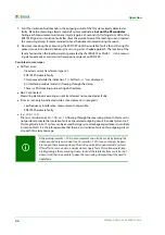
7. Start the insulation fault location in the outgoing circuit of the IT system already detected as
faulty. Place the measuring clamp around all system conductors,
but not the PE conductor
.
During each measurement wait one test cycle (approx. 30 seconds). A flashing alarm LED on the
EDS195P signals an insulation fault after (from the point of view of the locating current injector)
the measuring clamp. It recommended to have the buzzer activated during the search.
8. Now measure along the cable using the EDS195P until the insulation fault is found. During this
process move into sub-distribution systems using a star-shaped approach. The location of the
fault is found when the locating current generated by the IRDH575 or PGH47… in the measur-
ing clamp exceeds as a minimum the response value set on EDS195P.
Possible error messages
Self test error:
– Incorrect current transformer type set
– EDS195P hardware faulty
– Clamp moved while the indication ">>>Self test<<<" was displayed
– An interfering residual current is flowing through the clamp
– There is a PGH locating pulse acting on the clamp
No CT connected:
Measuring clamp or measuring current transformer not connected or faulty.
Error I
Δ
L
(can only be indicated while a measurement is in progress):
– Low frequency interference, measurement not possible
– EDS195P hardware faulty
I
Δ
n
>10 A / >1 A:
There is a residual current > 10 A or > 1 A flowing through the measuring clamp. In this case it is
not possible to locate the insulation fault on the related outgoing circuit. Residual currents of
this magnitude in an IT system can be caused by large system leakage capacitances or multiple
insulation faults. It is therefore possible that there is an insulation fault on this outgoing circuit
also with this alarm message.
At operating currents < 10 A a measurement can also be made by placing the
clamp around only one conductor. At currents > 10 A it may no longer be possi-
ble to open the measuring clamp. This risk is particularly apparent in DC systems.
If this effect occurs, under no circumstances apply force; this action would irrep-
arably damage the measuring clamp. Instead the related system must be shut
down. It will then be possible to open the measuring clamp without the need to
apply force.
Содержание EDS3090
Страница 6: ...Table of Contents 6 EDS309x_D00012_03_M_XXEN 11 2014...
Страница 26: ...Considerations prior to use 26 EDS309x_D00012_03_M_XXEN 11 2014...
Страница 62: ...Frequently Asked Questions 62 EDS309x_D00012_03_M_XXEN 11 2014...
Страница 65: ......
Страница 66: ......
Страница 67: ......


