


System description
14
EDS309x_D00012_03_M_XXEN/11.2014
3.2 Function of the system components
3.2.1
Locating current injector PGH18…
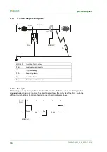
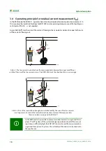
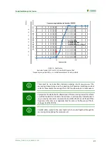
The PGH18… generates a defined locating current. The magnitude of the current is dependent on
the insulation fault present and the system voltage.
The PGH185 or PGH186 limits the locating current to maximum 25 mA or maximum 10 mA
depending on the switch setting.
The PGH183 limits the locating current to maximum 2.5 mA or maximum 1 mA depending on
the switch setting.
The PGH186 applies the locating current in electrically isolated IT systems or in IT systems with
a system voltage < 50 V using an integrated voltage source (DC 50 V). In IT systems with a sys-
tem voltage > 50 V the existing voltage in the system is used to drive the locating current.
3.2.2
Insulation fault locator EDS195P
The insulation fault locator EDS195P has the following measuring functions:
Insulation fault location
I
Δ
L
(EDS mode) for use in IT AC or DC systems:
– Either as a component of the portable equipment for insulation fault location EDS309…
– Or as an additional insulation fault locator in permanently installed equipment for insulation
fault location with IRDH575 or PGH1… as well as EDS46…/49….
Residual current measurement
I
Δ
n
(RCM mode) for usage in TN or TT AC systems. The response
value range can be found in table 3.1 on page 14.
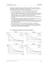
Response value
The response value is defined by the sensitivity of the EDS195P. This value can be set in both DC and
AC and 3AC IT systems as an arithmetic mean in accordance with Tabelle 3.1 auf Seite 14. System in-
terference and high system leakage capacitances can degrade the accuracy.
3.2.3
Measuring clamps
Measuring clamps measure the locating current or the residual current. They have a test lead approx.
2 m long. The connection to the EDS195P is made using a BNC connection.
The following table summarises the most important data for the usage of the different measuring
clamps.
Tab. 3.1: Measuring clamps and response values for the EDS195P
If measuring current transformers are used instead of measuring clamps, you will need the adapter
supplied: BNC/4-mm connector. See table on page 60.
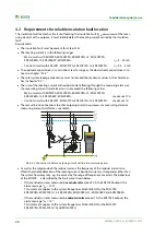
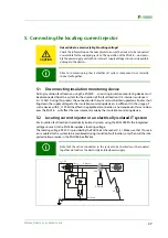
Main circuit
(EDS3090…, 3092…, 3096…)
Control circuit
(EDS3091…)
IT system
Measuring
clamps
PSA3020, PSA3052, PSA3165
PSA3320, PSA3352
Measuring range
2…50 mA
0.2…5 mA
Response value
2…10 mA,
±
30% /
±
2 mA
0.2…1 mA, ±30 % / ±0.2 mA
TN/TT system
Measuring
clamps
PSA3020, PSA3052, PSA3165
PSA3320, PSA3352
Measuring range
5 mA…10 A
2 mA…2 A
Response value
10 mA…10 A
5 mA…1 A
Содержание EDS3090
Страница 6: ...Table of Contents 6 EDS309x_D00012_03_M_XXEN 11 2014...
Страница 26: ...Considerations prior to use 26 EDS309x_D00012_03_M_XXEN 11 2014...
Страница 62: ...Frequently Asked Questions 62 EDS309x_D00012_03_M_XXEN 11 2014...
Страница 65: ......
Страница 66: ......
Страница 67: ......


