34
BEKOMAT® 33U / 33U CO
A
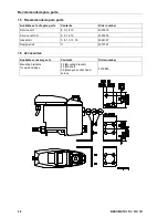
Accessories 28
Accessory sets 28, 29
Alarm mode 12
Angle adapter 27
B
blows off 26
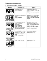
Both LEDs are continuously on 26
C
Circuit board 27
Climate zone
blue 10
green 10
red 10
Climate zones 10
Components 27
Condensate discharge disturbed 26
Control 20
D
Danger compressed air 4, 14, 20
Danger supply voltage 5, 17, 20
Data 7
Declaration of conformity 30
Deflector area 16
Degree of protection 5, 17, 20
Dimension drawing 9
Dimensions 9
E
Electric diagram 19
Electrical data 8
Electrical installation 17
Elements 27
Exclusion from the scope of application 6
Exclusion of a field of application 6
F
Failure 26
Fault clearance 26
Fault diagnosis 26
Fault elimination 26
Feed pipe 16
Field of application 6
Filling level 11
Function 11
I
Inlet line 11
Installation 14
Installation and operating instructions 4
Installation and operating instructions 4
Instructions, safety instructions 4
Intermediate adapter 27
L
Lower part of the cover 27
M
Maintenance 20
Maintenance recommendation 21
Malfunction 26
Membrane 11
Mounting 14
N
No condensate discharge 26
No LED lights up 26
O
Order number 28, 29
Outlet line 11
P
Performance data 10
Pictograms 4
Pilot valve 11
Pressure differences 16
Proper use 6
Q
Qualified personnel 5, 17, 20
R
Recommended spare parts 28
S
Safety instructions 4
Self-test 12
Sensor 27
Sensor tube plate 25
Service measures 4, 14, 20
Service unit 21, 27
Sets of spare parts 28
Slope 16
Spare parts 5, 28
Symbols 4
T
Technical data 7
Trouble sources 12
Troubleshooting 26
U
Upper part of the cover 27


