Electrical installation
BEKOMAT® 33U / 33U CO
19
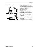
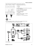
Terminal assignment of the potential-free contact and of the external test
X 1
X 2
X 3
Fault indication/potential-free contact:
• X 2.1 n.o.
• X 2.2 com.
• X 2.3 n.c.
n.c. - com. closed in the event of malfunction or power failure
(closed current principle)
n.o. - com. closed during normal operation
The contacts X2.1 - 2.3 are potential-free.
External test / remote control:
• X 3.1 external test (IN1)
• X 3.2 GND
Contacts connected = test active = discharge
Contacts open = test inactive
The contacts X 3.1 -3.2 are not potential-free.
L
/+
N
/-
N
O
C
O
N
C
IN
1
G
N
D
p
o
w
e
r
p
o
w
e
r
n
o
rm
a
lly
o
pe
n
co
m
m
o
n
n
o
rm
a
lly
cl
o
se
d
e
xt
e
rn
al
te
st
(I
N
1
)
G
N
D
1
.1
1
.2
2
.1
2
.2
2
.3
3
.1
3
.2
Note:
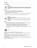
At a low-voltage supply (< 50 VAC / < 75 VDC), only use a protective extra-low-voltage.
Tighten the threaded cable connection with a slightly sealing effect.
Pos: 58 / Beko Technische Dok um ent at ion/ I nst allat ion/ B EKO M AT/ E- Sch em a @ 0\ m od_12337581781 63_290 1. docx @ 13497 @ @ 1
Electric diagram
Pos: 59 / - -- - Seit enum br uch - -- - @0\ m od_1157028099015_ 0. docx @ 2903 @ @ 1

