The EU-Type Examination Certificate has an 'X' suffix indicating that the
following special conditions for safe use apply. Practical implications are
explained in later sections of this instruction sheet.
SPECIAL CONDITIONS FOR SAFE USE
The equipment has an ingress protection rating of IP66. However,
if it has been supplied without cable entry devices, then the user
shall ensure that the devices that are fitted will provide an ingress
protection that is appropriate to the environment in which it is
installed i.e. IP20 or better.
The total capacitance connected to terminals + wrt - (i.e. the
capacitance of the cable plus any other capacitance) shall not
exceed 83nF.
The equipment shall not be directly installed in any process where
its enclosure might be electro-statically charged by the rapid flow
of a non-conductive media.
The equipment shall only be supplied via Terminals + w.r.t.
Terminals - from a barrier having a maximum open circuit voltage
Uo that is < 28V and a maximum short circuit current Io that is
< 93mA, where Io is resistively limited. The barrier or galvanic
isolator shall be ATEX certified by a notified body.
4.2
Zones
, Gas Groups and T rating
The BR385 sounder has been certified Ex ia IIC T4 Ga. When
connected to approved Zener barriers or galvanic isolators it may be
installed in:
Zone 0
explosive gas air mixture continuously present.
Zone 1
explosive gas air mixture likely to occur in normal
operation.
Zone 2
explosive gas air mixture not likely to occur, and if it
does, it will only exist for a short time.
Warning
Do not install the BR385 where it may accumulate
an electrostatic charge from a rapid flow of dry air.
Be used with gases in groups:
Group A
propane
Group B
ethylene
Group C
hydrogen
Having a temperature classification of:
T1
450ºC
T2
300ºC
T3
200ºC
T4
135ºC
4.3 Ter and -
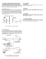
Power is supplied to the sounder via terminals + & - which have the
following maximum input safety parameters:
Ui
=
28V
Ii
=
93mA dc
Pi
=
0.66W
BR385 sounders may be powered from any ATEX Ex ia IIC certified Zener
barrier or galvanic isolator having output parameters equal to, or less
than, these limits. e.g. a certified 28V, 93mA, 0.66W Zener barrier or
isolator may be used.
The BR385 ATEX certificate specifies that the maximum permitted total
capacitance that may be connected between the + and - terminals shall
not exceed 83nF, irrespective of the Zener barrier or galvanic isolator
powering the sounder. This total capacitance includes the cable
capacitance plus the capacitance of any other connected device. This
should not be restrictive unless the sounder and the barrier or isolator are
a long way apart. Single pair instrumentation cables have a typical
capacitance of 100pF/metre rising to 350pF/metre for multicore cables
and are unlikely to exceed 600pF/metre allowing a cable length of up to
830, 230 or 138 metres respectively.
Up to three BR385 sounders may be connected in parallel and powered
from a common barrier or isolator providing the voltage between the + and
– terminals does not fall below 8V. Connecting two sounders in parallel
will reduce the output from each sounder by about 3dB. Three sounders
should only be powered from a common supply when the maximum
supply voltage is available.
4.4 Terminals S2 and S3
When terminals S2 or S3 are connected to 0V ( - terminal) the sounder
output tone changes to the second or third stage alarm respectively. The
input safety parameters for these terminals are:
Ui
=
28V
Ii
=
0mA
Therefore for control from the safe area terminals S2 & S3 may only be
connected to a certified diode return barrier, or the contacts of a certified
intrinsically safe relay. For functional reasons diode return barriers with a
voltage drop of less than 0.9V must be used. The maximum permitted
cable capacitance Co will be specified on the diode return barrier ATEX
certificate, but again should not be restrictive.
For control from the hazardous area terminals S2 & S3 may be directly
connected to a mechanically operated switch in the hazardous area
complying with the requirements for simple apparatus as defined in
EN 60079-11. i.e. having IP20 protection and able to withstand a 500V
rms insulation test to earth for one minute.
5. INSTALLATION
BR385 sounders should only be installed by trained competent personnel
.
5.1 Mounting
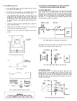
The BR385 sounder may be secured to any flat surface using the two
7mm diameter fixing holes. The enclosure provides IP66 protection and is
suitable for installation in sheltered exterior locations providing it is
positioned so that water can not collect in the horn, and the cable entry is
sealed.
2


