5.2 Installation procedure
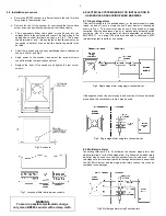
a. Secure the BR385 sounder to a flat surface via the two 7mm dia
fixing holes in the mounting feet.
b. Remove the front of the sounder by unscrewing the four captive
corner screws and pulling the front away from the enclosure.
c.
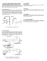
Fit an appropriate 20mm cable gland or conduit entry into the
untapped hole in the enclosure and connect the field wiring to the
appropriate sounder terminals as shown in Fig 3. The power
supply ter and – are duplicated so that sounders may be
connected in parallel, or an end-of-line monitoring resistor may
be fitted.
d.
Select the required output tone by positioning the six switches as
shown in Table 1 and Fig 3.
e.
Apply power to the sounder and adjust the internal volume
control to provide the required sound level.
f.
Replace the front of the sounder and tighten the four corner
screws.
Fig 2 Enclosure
Fig 3 Location of field terminals and controls.
6. ELECTRICAL SYSTEM DESIGN FOR INSTALLATION IN
HAZARDOUS AREAS USING ZENER BARRIERS
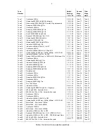
6.1 Single stage alarm
If the control switch is in the positive supply, or the power supply is being
turned on and off, only a single channel Zener barrier is required as
shown in Fig 4. This circuit may also be used if the sounder is being
controlled from the hazardous area by a mechanically activated switch
complying with the requirements for simple apparatus. as defined by
EN 60079-11. i.e. having IP20 protection and able to withstand a 500V
rms insulation test to earth for one minute.
Fig 4 Single stage alarm using single channel barrier.
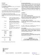
If the negative side or the power supply and one side of the control switch
are earthed, the circuit shown in Fig 5 may be used.
Fig 5 Single stage alarm using two channel barrier.
6.2 Multi-stage alarm
Connecting terminal S2 to 0V activates the second stage alarm, and
similarly terminal 3 for the third stage alarm. Fig 6 shows how diode return
barrier(s) may be used to control the sounder from the safe area. If only
two stages of alarm are required the third stage barrier should be omitted,
the 28V 93mA barrier and the single diode return channel may then be
contained in one package.
Fig 6 Multi-stage alarm using Zener barriers.
WARNING
To avoid a possible electrostatic charge
only clean BR385 sounder with a damp cloth.
3


