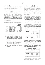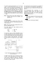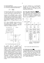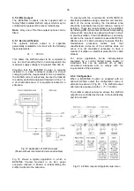
The second digit defines the deviation from the
displayed rate at which the filter will be overridden
and the rate display will move rapidly to the new
value.
Second
digit
Magnitude of step
change which will
produce a rapid
response
X0
Off
X1
1%
X2
2%
X3
4%
X4
8%
X5
12%
X6
16%
X7
24%
X8
32%
X9
64%
By careful adjustment of the two parameters a stable
display with an acceptable input step response can
be obtained for most applications.
During commissioning it is recommend that initially
the second digit is set to
0
(off) and the first digit is
adjusted to provide acceptable rate display stability.
The second digit should then be increased until the
selected step size is greater than the noise on the
display signal, at which setting the rate display will
become stable. These will be the optimum filter
parameters for acceptable rate display stability and a
fast response to a large rate signal change.
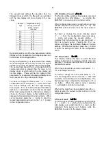
To check or change the filter select
FiLtEr
in the
configuration menu and press
(
which will reveal
the current settings with the first digit flashing.
Pressing the
&
or
*
button will adjust the flashing
digit and
(
will transfer control to the second digit.
While making adjustments the filtered rate display is
shown on the lower display so that stability can be
assessed while adjustments are being made. When
set as required, press the
)
button to enter the
revised parameters and return to the
FiLtEr
prompt
in the configuration menu.
6.16 Direction of count:
uP or dn
This function defines whether input pulses increment
or decrement the total display. i.e. whether the
BA367NE is an up-counter or a down-counter.
When configured as a down-counter with a non-zero
number entered for the reset value
CLr VAL
, the
BA367NE will count down from the reset value to
zero.
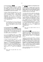
To check or change the count direction select
uP or dn
from the configuration menu and press
(
which will reveal the present setting.
uP
indicates that the instrument is an up-counter and
dn
that it is a down counter. Pressing the
&
or
*
buttons will toggle the instrument between the two
settings. When set as required, press the
)
button
to enter the setting and return to the configuration
menu.
6.17 Reset value:
CLr VAL
This function defines the value to which the total
display is reset when the local or remote reset are
operated. This allows the BA367NE to be used as a
preset down-counter.
When the instrument is used as an up-counter,
CLr
VAL
is normally set to zero.
To check or change the reset value select
CLr VAL
from the configuration menu and press
(
which will
reveal the current setting with one digit flashing. The
flashing digit may be adjusted by pressing the
&
or
*
button. When this digit is correct, pressing
(
will transfer control to the next digit.
When all the digits have been adjusted press the
)
button to enter the revised number and return to the
configuration menu.
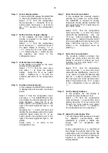
6.18 Local reset:
LoC CLr
The Local reset function contains two sub-functions
Clr tot
and
Clr Gtot
which when enabled allow the
total display and grand total to be reset via the
instrument front panel push buttons while the
BA367NE Counter is in the display mode.
21
Содержание BA364G
Страница 1: ...Issue 7 9th July 2019 BA367NE One input Ex nA and Ex tc Counter Issue 7 ...
Страница 16: ...16 ...
Страница 17: ...17 ...


