9. ACCESSORIES
9.1 Scale card
The BA367NE Counter has a window on the right
hand side of the display through which a scale card
showing the units of measurement is visible. New
Counters are fitted with a scale card showing the
units of measurement specified when the instrument
was ordered, if the units are not specified a blank
scale card will be fitted. A pack of scale cards pre-
printed with common units of measurement is
available as an accessory. These can easily be
fitted to the Counter on-site without opening the
instrument enclosure or removing it from the panel,
See section 5.5 of this instruction manual.
Custom scale cards for applications requiring less
common units of measurement are also available.
9.2 Tag information
New Counters can be supplied with a tag number or
application information laser etched onto the rear
panel adjacent to the terminals. This information is
not visible from the front of the instrument after
installation.
9.3 Alarms
The BA367NE can be supplied with factory fitted
dual solid state, single pole alarm outputs that may
be independently programmed as high or low, rate or
total alarms with normally open or normally closed
outputs.
Note:
Only one of the three output options can be
fitted.
Configurable functions for each alarm include
adjustable setpoint, alarm delay time and alarm
silence time. Hysteresis may be applied to rate
alarms.
CAUTION
Alarm outputs should not be used for
critical safety applications such as a shut
down system.
When the BA367NE Counter power supply is turned
off or disconnected, the alarm outputs will open
irrespective of whether normally open or normally
closed outputs have been selected. When designing
a system an open output should therefore be chosen
for the alarm condition.
Alarm annunciators on the instrument display
indicate the status of each alarm. If an alarm delay
or silence time has been selected the annunciator
will flash during the delay or silence period.
The BA367NE internal counters are up-dated and
compared with the alarm setpoint twice per second,
irrespective of the display update time selected.
This may result in an alarm being delayed for up to
half a second after the rate or total has exceeded the
setpoint.
9.3.1 Solid state output
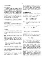
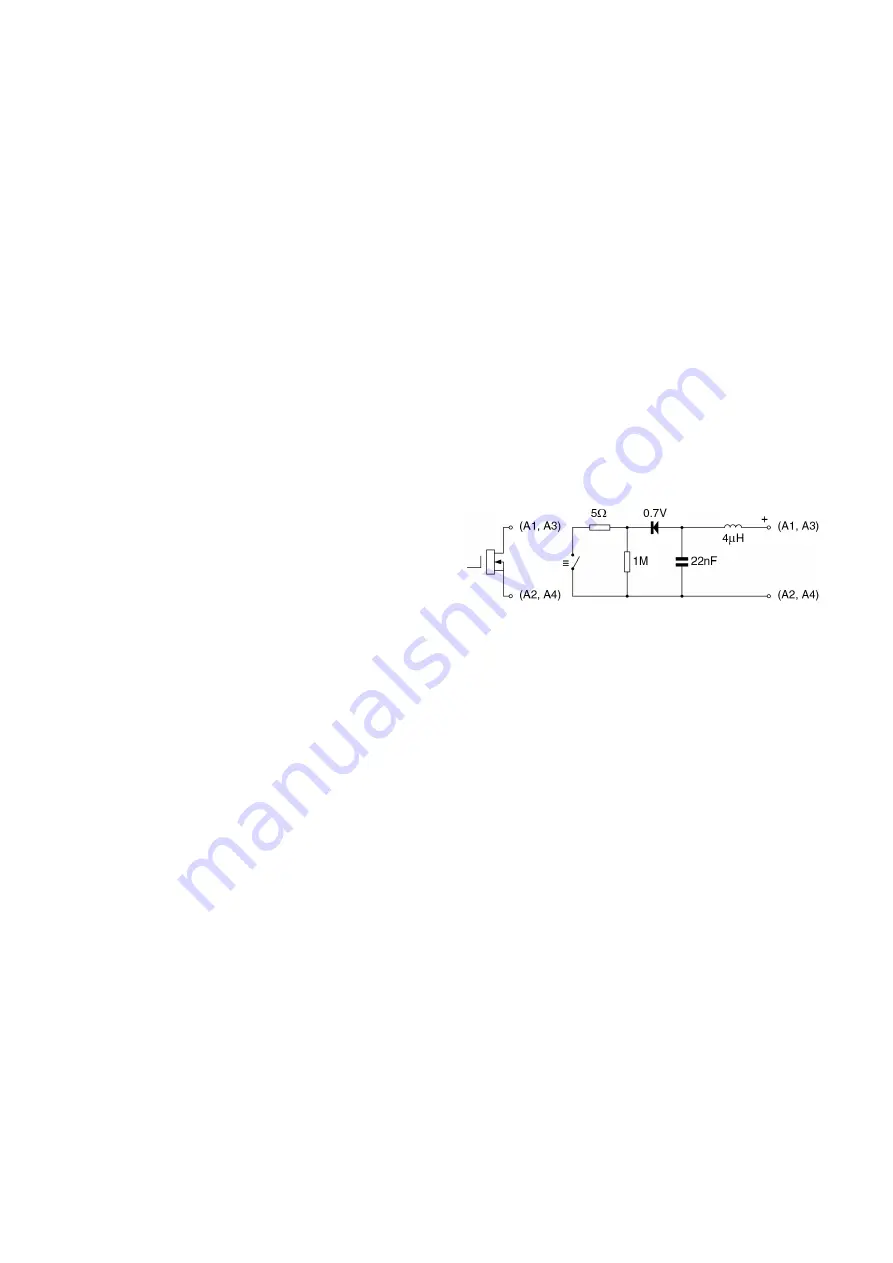
Each alarm has a galvanically isolated single pole
solid state switch output as shown in Fig 12. The
outputs are polarised and current will only flow in
one direction. Terminals A1 and A3 should be
connected to the positive side of the supply.
Ron
=
less than 5
+ 0.7V
Roff
=
greater than 1M
Note:
Because of the series protection diode some
test meters may not detect a closed alarm
output.
Fig 12 Equivalent circuit of each alarm output
9.3.2 Type nA certification
Each alarm output is a separate galvanically isolated
Ex nA circuit with the following input parameters:
Ui
=
30V dc
Ii
=
200mA
This allows each alarm output to switch any dc
circuit providing that in normal operation the
maximum supply voltage is not greater than 30V dc
and the switched current is not greater than 200mA.
Providing that the BA367NE Counter is correctly
installed in a panel enclosure located in Zone 2
complying with the requirements for Ex n protection,
the two alarm outputs may be used to switch suitably
protected equipment located in Zone 1 or 2 of a
hazardous area, or equipment located in a safe
area.
Fig 13 shows a typical application in which a
BA367NE Counter, mounted in an Ex n panel
enclosure located in Zone 2, is displaying the output
from a Flameproof Ex d 2-wire flowmeter located in
Zone 1. Alarm 1 is switching an Ex e sounder in
Zone 1 and alarm 2 is switching a sounder located in
the safe area.
28
Содержание BA364G
Страница 1: ...Issue 7 9th July 2019 BA367NE One input Ex nA and Ex tc Counter Issue 7 ...
Страница 16: ...16 ...
Страница 17: ...17 ...


