Documentation
KL85xx und KL9309
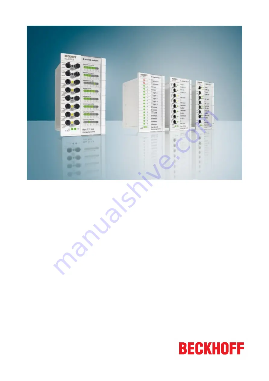
Manual operating modules with K-Bus interface
2.1.02018-02-27
Version:Date:
Страница 1: ...Documentation KL85xx und KL9309 Manual operating modules with K Bus interface 2 1 0 2018 02 27 Version Date...
Страница 2: ......
Страница 3: ...6 1 KL8548 Introduction 18 2 6 2 Technical data 19 2 7 KL9020 20 2 7 1 KL9020 End terminal with K bus extension 20 2 7 2 Technical data 21 2 8 KL9309 22 2 8 1 KL9309 Introduction 22 2 8 2 Technical da...
Страница 4: ...5 1 1 KL8519 Process image 62 5 1 2 KL8519 control and status bytes 62 5 1 3 KL8519 Register overview 64 5 1 4 KL8519 Register description 64 5 2 KL8524 67 5 2 1 KL8524 Process image 67 5 2 2 KL8524 c...
Страница 5: ...of the data diagrams and descriptions in this documentation Trademarks Beckhoff TwinCAT EtherCAT Safety over EtherCAT TwinSAFE XFC and XTS are registered trademarks of and licensed by Beckhoff Automa...
Страница 6: ...re familiar with the applicable national standards Description of symbols In this documentation the following symbols are used with an accompanying safety instruction or note The safety instructions m...
Страница 7: ...cted Chapter Connection extended Libraries updated 1 1 0 Register descriptions updated Technical data updated 1 0 0 First release Firmware and hardware versions Documentation Version KL8500 KL8519 KL8...
Страница 8: ...Foreword KL85xx und KL9309 8 Version 2 1 0 33 week of production 33 06 year of production 2006 B1 firmware version B1 00 hardware version 00...
Страница 9: ...via the user program See chapter Control and status bytes of the respective module The manual operating modules can be installed in the control cabinet door using a snap in technique they are wired i...
Страница 10: ...tion file TcTerminals is used The current bus terminal configuration file is available from the Beckhoff website under Download Configuration files Bus Terminals 2 2 KL8500 2 2 1 KL8500 Introduction F...
Страница 11: ...x 127 5 mm x 75 mm external dimensions see Mounting 26 for installation dimensions Mounting Installation in the control cabinet door Permissible ambient temperature range during operation 0 C 55 C Pe...
Страница 12: ...The KL8519 is a 16 channel digital input signal module 16 digital inputs can be connected which indicate their status via LEDs and transmit the data to the controller The LEDs are bicolor LEDs in the...
Страница 13: ...byte Input process image 6 bytes data 1 status byte Weight approx 150 g Dimensions W x H x D 71 mm x 127 mm x 69 mm external dimensions see Mounting for installation dimensions Mounting 26 Installati...
Страница 14: ...x 2 channel digital output module equipped with two switches The first is for switching between manual and automatic operation while the second is used to set a 2 stage output It is possible to speci...
Страница 15: ...process image 6 bytes data 1 control byte Input process image 6 bytes data 1 status byte Weight approx 160 g Dimensions W x H x D 71 mm x 127 mm x 69 mm external dimensions see Mounting for installat...
Страница 16: ...uction Fig 5 KL8528 8 channel digital output module The KL8528 is an 8 channel digital output module The outputs can be switched via a switch or specified by the controller The status is indicated by...
Страница 17: ...mage 6 bytes data 1 control byte Input process image 6 bytes data 1 status byte Weight approx 160 g Dimensions W x H x D 71 mm x 127 mm x 69 mm external dimensions see Mounting for installation dimens...
Страница 18: ...ut module 0 10 V The KL8548 is an 8 channel analog output module for 0 10 V The analog values must be specified individually for each channel via the controller or via a potentiometer The actual outpu...
Страница 19: ...isplayed in the form of bar graphs Electrical isolation 500 V K bus Power consumption Us typically 50 mA in ECO Mode 95 mA in Full Scale Mode Output process image 16 byte data 8 control bytes Input pr...
Страница 20: ...ion of an Ethernet cable with a RJ 45 connector The K bus signals are converted to RS485 The supply is via the K bus Apart from a supply voltage of 24 V and the insertion of the Ethernet cable there i...
Страница 21: ...ate K bus Weight approx 45 g Dimensions W x H x D approx 26 mm x 100 mm x 70 mm Mounting 27 on 35 mm mounting rail according to EN 60715 Permissible ambient temperature range during operation 0 C 55 C...
Страница 22: ...be connected to the manual operating module via a system cable using a 20 pole pin contact strip with locking The KL9309 has a modular design and can be incorporated seamlessly on the DIN rail K bus c...
Страница 23: ...inal 24 mm x 100 mm x 68 mm without plug connector Mounting 27 on 35 mm mounting rail according to EN 60715 Permissible ambient temperature range during operation 0 C 55 C Permissible ambient temperat...
Страница 24: ...24 Version 2 1 0 Rear side Fig 10 LEDs Meaning of the LED displays LED Color State and significance on off RUN green Lit either weakly or strongly K bus communication OK No K Bus communication ERR re...
Страница 25: ...rsion 2 1 0 3 Mounting and wiring 3 1 Dimensions Fig 11 Dimensions Note Mounting cut out and connector The mounting cut out 26 should have a size of 67 mm x 116 2 mm Make sure that there is sufficient...
Страница 26: ...mounting cut out should have a size of 67 mm x 116 2 mm Fig 12 Mounting cut out Note Positioning depends on the wall thickness of the mounting surface The figure shows that different mounting heights...
Страница 27: ...us Coupler Join the compo nents with tongue and groove and push the terminals against the mounting rail until the lock clicks onto the mounting rail If the Terminals are clipped onto the mounting rail...
Страница 28: ...ponents The six spring contacts of the K Bus E Bus deal with the transfer of the data and the supply of the Bus Terminal electronics The power contacts deal with the supply for the field electronics a...
Страница 29: ...rge to the PE line during insulation testing of a consumer with a nominal voltage of 230 V For insulation testing disconnect the PE supply line at the Bus Coupler or the Power Feed Terminal In order t...
Страница 30: ...cted 8 Set the Function Switch on all Coupler Terminals KL85xx KL9050 correctly Function Switch Activate the terminating resistor at the last expansion terminal block of your K bus extension system by...
Страница 31: ...embled un til it protrudes loosely The lock with the mounting rail is now released for this terminal and the termi nal can be pulled from the mounting rail without excessive force 4 Grasp the released...
Страница 32: ...erminals Attention Link the ground connections of the power supply units of the Bus Coupler and all manual operating modules with a low resistance connection For interference proof operation of the K...
Страница 33: ...diagram for the 20 pin connector on the rear side of the KL8519 Fig 19 KL8519 Connecting the 20 pin connector KL8524 Connection diagram for the 20 pin connector on the rear side of the KL8524 Fig 20...
Страница 34: ...0 Fig 21 KL8528 Connecting the 20 pin connector KL8548 Connection diagram for the 20 pin connector on the rear side of the KL8548 Fig 22 KL8548 Connecting the 20 pin connector KL9309 Connection diagra...
Страница 35: ...ir original size 3 8 Ordering information K bus extension Order designation Description KL9020 End Terminal with RJ45 socket 20 for K bus extension ZK1090 0101 1005 K bus extension cable with two plug...
Страница 36: ...oth ends for KL85xx KL9309 and terminals with ribbon cable connection length 3 m shielded ZK8500 8282 7040 PVC cable 20 x 0 14 mm plug connector at both ends for KL85xx KL9309 and terminals with ribbo...
Страница 37: ...or Bus Terminal Controllers from the BXxx00 series Standard lbx Note Memory usage Some of the PLC program memory is already used up by integrating the library Depending on the application program ther...
Страница 38: ...ck for the configuration of the KL8524 for reading out the digital signals and for setting the outputs LEDs FB_KL8528 45 Function block for configuration of the KL8528 for reading out the digital sign...
Страница 39: ...D will be green if 1 the LED will be red If the input is not occupied the LED remains off The variable wInv inverts the behavior of the LED If the input is FALSE the LED turns on if TRUE the LED turns...
Страница 40: ...ard function 59 of the LED must have been disabled with wDisCh dwOpt For future options wLEDGn Bit 0 TRUE bit 15 TRUE sets the green LEDs provided that the standard function 59 of the LED has been dis...
Страница 41: ...EDYe Each LED can be changed individually here The respective output can be set to TRUE with byKBusOff in the event of a K bus error or PLC stopped and switch position auto Bit 0 7 for the outputs 1 8...
Страница 42: ...nfiguration Switching time for channel 3 output mode 2 1 bit 10 ms with default 255dec FFhex the second output is switched on after 2550 ms if the three step switch is in position 2 byTurnOnDelayCh4 C...
Страница 43: ...8524Ex Fig 26 Function block FB_KL8524Ex Application This function block is used to configure the KL8524 to read out the digital signals and to set the outputs LEDs The function block must be called o...
Страница 44: ...itch is in position 2 following a delay which can be set with byTurnOnDelayChx byTurnOnDelayCh1 Configuration Switching time for channel 1 output mode 2 1 bit 10 ms with default 255dec FFhex the secon...
Страница 45: ...the signals for the graphic programming languages bManModelsDis Manual operating mode disabled wFirmVer Issues the firmware version bErr The bError output goes TRUE as soon as an error occurs This err...
Страница 46: ...tput 1 bit 7 output 8 in the event of a K bus error or PLC stopped provided that the switch is set to auto byOut Bit 0 TRUE Bit 7 TRUE sets the respective output provided the switch is set to auto All...
Страница 47: ...ith a positive edge on bExecCfg The variable byDisCh switches the standard function of the LEDs off The LEDs can now be switched independently of the digital input signal via the PLC with the variable...
Страница 48: ...disabled with byDisCh All yellow LEDs are set with 255dec FFhex The FB_KL85xx8BitToByte function block is available for preparing the signals for the graphic programming languages bDisManMode Disablin...
Страница 49: ...nfigurations bDisWatchdog bEnEcoMode bEnPwrOnVal and wPwrOnVal are written to the terminals when a positive edge is encountered bBusy goes TRUE Note that the inputs are not updated during this time bD...
Страница 50: ...bError output goes TRUE as soon as an error occurs This error is described via the udiErrID variable udiErrID In the event of an error the output issues an error code see error codes 59 bError goes TR...
Страница 51: ...us error or PLC stopped the analog output is set to the value of wPowerOnValue if bDisWatchdog True wPwrOnVal Configuration Value that the output is to adopt in the event of a K bus error or PLC stopp...
Страница 52: ...n from 16 bits to 1 Word FB_KL85xx8BitToByte 53 Conversion from 8 bits to 1 byte FB_KL85xxByteTo8Bit 54 Conversion from 1 byte to 8 bits FB_KL85xxWordTo16Bit 54 Conversion from 1 word to 16 bits 4 2 5...
Страница 53: ...UT wOut WORD wOut Word composed of the 16 bits 4 2 5 2 FB_KL85xx8BitToByte Fig 32 Function block FB_KL85xx8BitToByte Application This function block converts 8 bits to 1 byte VAR_INPUT b01 BOOL b02 BO...
Страница 54: ...This function block converts 1 byte to 8 bits VAR_INPUT byIn BYTE byIn Byte to be broken down into 8 bits VAR_OUTPUT b01 BOOL b02 BOOL b03 BOOL b04 BOOL b05 BOOL b06 BOOL b07 BOOL b08 BOOL b01 Bit 0 b...
Страница 55: ...it 9 b11 Bit 10 b12 Bit 11 b13 Bit 12 b14 Bit 13 b15 Bit 14 b16 Bit 15 4 3 Data types Hardware types Data type Description ST_KL8519InData 56 Process image of the inputs for the KL8519 ST_KL8519OutDat...
Страница 56: ...519_Watchdog1000ms The last state of the LED toggles every 1000 ms If the last state was OFF the LED remains OFF 4 3 2 ST_KL8519InData Process image of the inputs for the KL8519 Linked to the terminal...
Страница 57: ...he physical outputs bit 0 channel 1 output 1 bit 1 channel 1 output 2 bit 6 channel 1 output 1 bit 7 channel 4 output 2 4 3 5 ST_KL8524OutData Process image of the outputs for the KL8524 Linked to the...
Страница 58: ...byte 2 reserved for register communication byLEDOutGreen Data byte 3 sets LED 1 to 8 to green must be enabled via byDisCh byLEDOutYellow Data byte 4 sets LED 1 to 8 to yellow must be enabled via byDi...
Страница 59: ...unction block FB_KL8524 41 tries to set the outputs 1 and 2 simultaneously on channel 3 That is not allowed No output is set 0x8007 32775 The function block FB_KL8524 41 tries to set the outputs 1 and...
Страница 60: ...tive output is then FALSE even if it is set by the PLC The LEDs flash green if the automatic switch is set to man The respective output is then TRUE This functionality can be disabled with the variabl...
Страница 61: ...ming in TwinCAT KL85xx und KL9309 61 Version 2 1 0 The display mode can be selected separately for each analog value by writing to register R32 4 86 or with the function blocks FB_KL8548 49 or FB_KL85...
Страница 62: ...D 9 to 16 5 Byte reserved reserved 5 1 2 KL8519 control and status bytes Channel 1 Process data mode Control byte 1 in process data mode Control byte 1 CB1 is located in the output image 62 and is tra...
Страница 63: ...r number Enter the number of the register that you want to read with input data word DataIN1 62 or want to write with output data word DataOUT1 62 Status byte 1 in register communication The status by...
Страница 64: ...ec R W SEEPROM R17 reserved R30 reserved R31 65 Code word register 0x0000 0dec R W RAM R32 65 Disable Channel LED 0x0000 0dec R W SEEPROM R33 65 LED Color 0x0000 0dec R W SEEPROM R34 66 Inv LED 0x0000...
Страница 65: ...13 R32 12 R32 11 R32 10 R32 9 R32 8 Name disLED_Ch16 disLED_Ch1 5 disLED_Ch1 4 disLED_Ch13 disLED_Ch12 disLED_Ch11 disLED_Ch10 disLED_Ch9 Bit R32 7 R32 6 R32 5 R32 4 R32 3 R32 2 R32 1 R32 0 Name disL...
Страница 66: ...Ch16 in vLED_Ch15 in vLED_Ch14 invLED_Ch13 invLED_Ch12 invLED_Ch11 invLED_Ch10 invLED_Ch9 Bit R34 7 R34 6 R34 5 R34 4 R34 3 R34 2 R34 1 R34 0 Name invLED_Ch8 invLED_Ch7 invLED_Ch6 invLED_Ch5 invLED_Ch...
Страница 67: ...OFF reaction Key Bit Name Description default R36 15 reserved 0bin R36 2 reserved 0bin R36 1 R36 0 K bus OFF reaction 00bin In the event of a K bus error all LEDs that have been set via the PLC R32 r...
Страница 68: ...trols this channel 2 enAutoC3 0bin auto man switch of channel 3 is set to man the three step switch controls this channel 1bin auto man switch of channel 3 is set to auto the PLC controls this channel...
Страница 69: ...0 01bin Position 1 10bin Position 2 11bin Position 0 3 and 2 Channel 2 See channel 1 5 and 4 Channel 3 See channel 1 7 and 6 Channel 4 See channel 1 since switch position 3 does not exist the channel...
Страница 70: ...B1 3 CB1 2 CB1 1 CB1 0 Name RegAccess Key Bit Name Description CB1 7 RegAccess 0bin Register communication off process data mode CB1 6 CB1 0 0bin reserved Status byte 1 in process data mode The status...
Страница 71: ...data word DataOUT1 67 Status byte 1 in register communication The status byte 1 SB1 is located in the input image 67 and is transmitted from terminal to the controller Bit SB1 7 SB1 6 SB1 5 SB1 4 SB1...
Страница 72: ...1 Signal channels R ROM R12 73 minimum data length of a channel R ROM R13 Data structure R ROM R14 reserved R15 Alignment register R W RAM R16 73 Hardware version number e g 0x0000 e g 0dec R W SEEPRO...
Страница 73: ...irmware version Register R9 contains the ASCII coding of the terminal s firmware version e g 0x3141 1A The 0x31 corresponds here to the ASCII character 1 while the 0x41 represents the ASCII character...
Страница 74: ...KBOR_Ch4 KBOR_Ch3 KBOR_Ch2 KBOR_Ch1 Key Bit Name Description default R33 15 reserved 0bin R33 8 reserved 0bin R33 7 K bus OFF Reac tion_Ch4 2 0bin In the event of a K bus error output 4 2 is reset 0b...
Страница 75: ...itch position 2 to switch position 1 Fast switching from 0 to 2 or from 2 to 0 always takes place via switch position 1 and thus also starts the delay time Examples Output 1 switches on immediately wh...
Страница 76: ...rts again if the switch is switched from 1 to 2 when the delay time is running R38 Output mode switch on delay for channel 2 See register 37 R39 Output mode switch on delay for channel 3 See register...
Страница 77: ...off 1bin Switch of channel 1 is set to on 1 Switch1 0bin Switch of channel 2 is set to off 1bin Switch of channel 2 is set to on 7 Switch1 0bin Switch of channel 8 is set to off 1bin Switch of channe...
Страница 78: ...ss Key Bit Name Description CB1 7 RegAccess 0bin Register communication off process data mode CB1 6 CB1 0 0bin reserved Status byte 1 in process data mode The status byte 1 SB1 is located in the input...
Страница 79: ...data word DataOUT1 76 Status byte 1 in register communication The status byte 1 SB1 is located in the input image 76 and is transmitted from terminal to the controller Bit SB1 7 SB1 6 SB1 5 SB1 4 SB1...
Страница 80: ...are version number e g 0x0000 e g 0dec R W SEEPROM R17 reserved R30 reserved R31 81 Code word register 0x0000 0dec R W RAM R32 81 Disable Channel LED 0x0000 0dec R W SEEPROM R33 81 K bus off reaction...
Страница 81: ...2 1 R32 0 Name disLED_Ch8 disLED_Ch7 disLED_Ch6 disLED_Ch5 disLED_Ch4 disLED_Ch3 disLED_Ch2 disLED_Ch1 Key Bit Name Description default R32 15 reserved 0bin R32 8 reserved 0bin R32 7 disLED_Ch8 0bin T...
Страница 82: ...ut and output data These are organized as follows Byte offset without word alignment Byte offset with word align ment Format Input data Output data 0 0 Byte SB1 83 CB1 83 1 2 Word DataIN1 DataOUT1 3 4...
Страница 83: ...0 V 0x3FFF 16383 5 V 0x7FFF 32767 10 V 5 4 2 KL8548 control and status bytes Channel 1 Process data mode Control byte 1 in process data mode Control byte 1 CB1 is located in the output image 82 and is...
Страница 84: ...t Name Description CB1 7 RegAccess 1bin Register communication switched on CB1 6 R W 0bin Read access 1bin Write access CB1 5 to CB1 0 Reg no Register number Enter the number of the register that you...
Страница 85: ...e g 0x0000 e g 0dec R W SEEPROM R17 reserved R30 reserved R31 86 Code word register 0x0000 0dec R W RAM R32 86 Feature register 0x0004 4dec R W SEEPROM R33 86 User scaling offset 0x0000 0dec R W SEEP...
Страница 86: ...tch various features for this channel on or off Bit R32 15 R32 14 R32 13 R32 12 R32 11 R32 10 R32 9 R32 8 Name enUserValue Bit R32 7 R32 6 R32 5 R32 4 R32 3 R32 2 R32 1 R32 0 Name enEcoMode enWatchdog...
Страница 87: ...inal returns the firmware version 0x3341 in the input data word byte 1 and byte 2 This is to be interpreted as an ASCII code ASCII code 0x33 represents the digit 3 ASCII code 0x41 represents the lette...
Страница 88: ...us byte Byte 1 DataIN1 high byte Byte 2 DataIN1 low byte 0x9F 1001 1111bin 0x12 0x35 Explanation The terminal returns the value of the control byte as a receipt in the status byte The terminal returns...
Страница 89: ...inal Byte 0 Status byte Byte 1 DataIN1 high byte Byte 2 DataIN1 low byte 0xA0 1010 0000bin 0x00 0x02 Explanation The terminal returns the value of the control byte as a receipt in the status byte The...
Страница 90: ...ckhoff components there Beckhoff Headquarters Beckhoff Automation GmbH Co KG Huelshorstweg 20 33415 Verl Germany Phone 49 0 5246 963 0 Fax 49 0 5246 963 198 e mail info beckhoff com Beckhoff Support S...
Страница 91: ...ly with low resistance ground connection 32 Fig 19 KL8519 Connecting the 20 pin connector 33 Fig 20 KL8524 Connecting the 20 pin connector 33 Fig 21 KL8528 Connecting the 20 pin connector 34 Fig 22 KL...