Product overview
EP1518-0002
10
Version: 2.4
3
Product overview
3.1
Introduction
Tx+ / GND
Rx+ / GND
Rx- / U
Tx- / U
1 |
2 |
3 |
4 |
S
P
P
S
1 |
2 |
3 |
4 |
5 |
+24 V U
Input B
GND
Input A
n.c.
S
Digital inputs,
Counter inputs
1 |
2 |
3 |
4 |
+24 V Us
+24 V Up
GND
GND
EtherCAT downstream connection
Supply voltage
input
EtherCAT input
Supply voltage
downstream connection
8 digital inputs (24 V
DC
), 2 counters
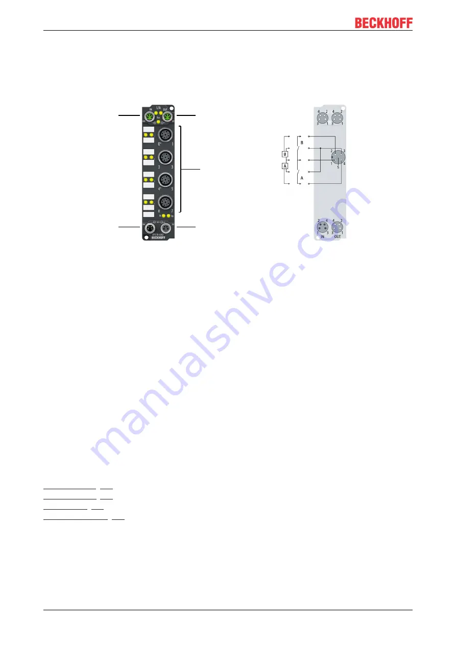
The EP1518-0002 EtherCAT Box with digital inputs acquires binary control signals from the process level
and transfers them, with electrical isolation, to the controller.
The signal state is indicated by means of light emitting diodes. Connection is via M12 connectors. The input
filters can be set between 0 and 100 ms via EtherCAT.
Inputs 0 and 4 can be used as up/down counters (32-bit). Inputs 1 and 5 operate as GATES and inputs 2
and 6 control Up/Down.
The EP1518 has three modes of operation that can be selected via the PDOs using the Sync-Manager:
• 2 digital inputs and 2 counters (delivery state)
• 5 digital inputs and 1 counter
• 8 digital inputs
All inputs continue to be shown in the process image even in the counter operation modes. Signal acquisition
takes place with the filter times set via CoE.
Irrespective of that, the counter pulses are always counted with a filter of 150 µs. Further parameters can be
set via the CoE objects.
The sensors are supplied via the control voltage US in two groups of four sensors each. Any short circuits on
the sensor side are detected and reported to the controller.
The load voltage Up is not used in the input module, but may optionally be connected in order to be relayed
downstream.
Quick links


