


Appendix
EL6692
146
Version: 3.2
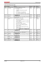
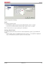
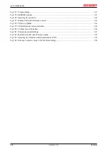
Fig. 179: FPGA firmware version definition
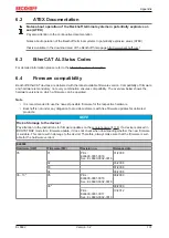
If the column
Reg:0002
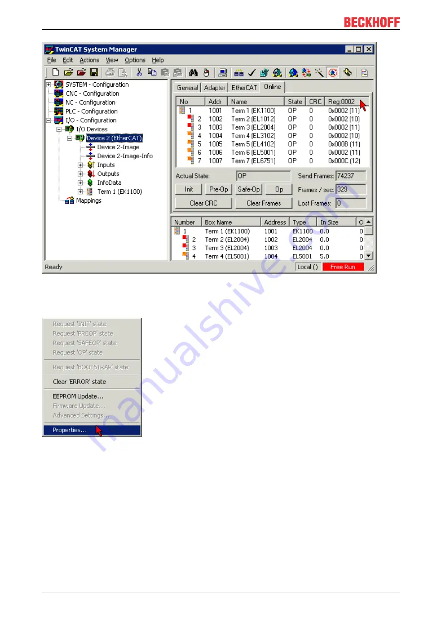
is not displayed, right-click the table header and select
Properties
in the context
menu.
Fig. 180: Context menu
Properties
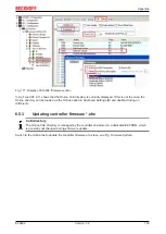
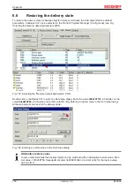
The
Advanced Settings
dialog appears where the columns to be displayed can be selected. Under
Diagnosis/
Online View
select the
'0002 ETxxxx Build'
check box in order to activate the FPGA firmware
version display.
Содержание EL6692
Страница 1: ...Documentation EL6692 EtherCAT Bridge Terminal 3 2 2020 03 03 Version Date...
Страница 2: ......
Страница 72: ...Commissioning EL6692 72 Version 3 2 Fig 74 Incorrect driver settings for the Ethernet port...
Страница 83: ...Commissioning EL6692 83 Version 3 2 Fig 93 EtherCAT terminal in the TwinCAT tree left TwinCAT 2 right TwinCAT 3...


