Extended functions
BK3xx0
78
Version: 4.3.0
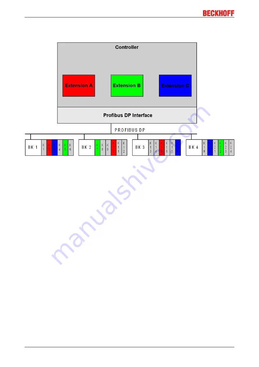
associated with the machine. A machine, with machine extensions A, B and C, whose process signals are to
be read or output over the PROFIBUS DP through Beckhoff Bus Couplers BK3110, BK3120 or BK3520,
could be structured as follows.
Fig. 46: Representation of a production machine
The machine illustrated consists of a controller (e.g. TwinCAT, S7-400, etc.), a PROFIBUS DP master
interface (e.g. FC3101, CP???, etc.) that sends or receives the process signals over the PROFIBUS DP, and
of Bus Couplers with Bus Terminals that form the interface to the machine process. The areas shown in grey
relate to machine parts that are always present. The machine extensions A, B and C are shown in red, green
and blue. It can be seen that each machine extension is associated both with software modules within the
control program and process signals that are connected to the controller via Bus Terminals.
Because the machine builder will not want to maintain eight different control programs for all possible
combinations of the machine extensions, it is helpful if the control program is designed in such a way that the
necessary software modules are activated according to whichever machine extensions are in fact being
used. In order to create a control program suited to all implementation levels of the machine it is however
necessary for the same process signals always to appear at the same addresses in the controller's process
image, independently of which process signals are in fact present in the relevant implementation level. For
conventional DP slaves, a different configuration of the PROFIBUS DP master interface is necessary in such
cases. The following sections explain how this problem can be solved with Beckhoff Bus Couplers, using a
single configuration of the PROFIBUS DP master interface.
The advantage of this solution is that two machine configurations only differ in terms of the hardware used
(machine components and Bus Terminals), but not in terms of the software. If the machine is upgraded, it is
only necessary for the additional Bus Terminals to be inserted and wired-up, and for the relevant extension
to be activated (e.g. via the man-machine interface to the machine). Software changes are no longer
required.
Process image interfaces
The interfaces between controller, PROFIBUS DP master interface, Bus Coupler and Bus Terminals form
process images, in which the process signals are stored according to certain algorithms.
Содержание BK3 0 Series
Страница 1: ...Documentation BK3xx0 Bus Coupler for PROFIBUS DP 4 3 0 2019 04 03 Version Date...
Страница 2: ......
Страница 11: ...Product overview BK3xx0 11 Version 4 3 0 2 2 BK3150 Technical data Fig 2 BK3150 Bus Coupler for PROFIBUS DP...
Страница 83: ...Extended functions BK3xx0 83 Version 4 3 0 Fig 50 State transitions in the Bus Coupler...


